Monoprolellant/hypergolic powered proportional actuator
- Summary
- Abstract
- Description
- Claims
- Application Information
AI Technical Summary
Benefits of technology
Problems solved by technology
Method used
Image
Examples
first embodiment (figs.1a-1c)
[0043] First Embodiment (FIGS. 1A-1C)
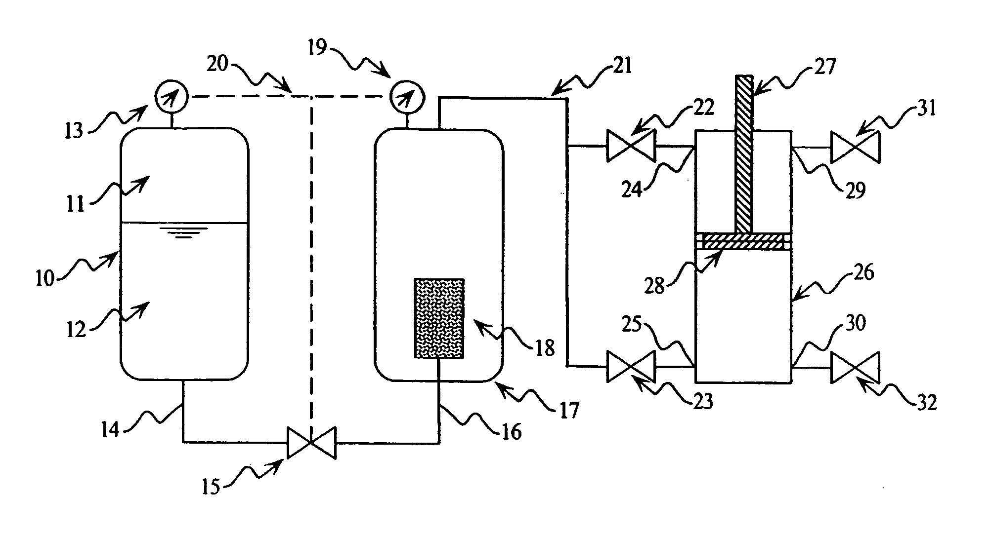
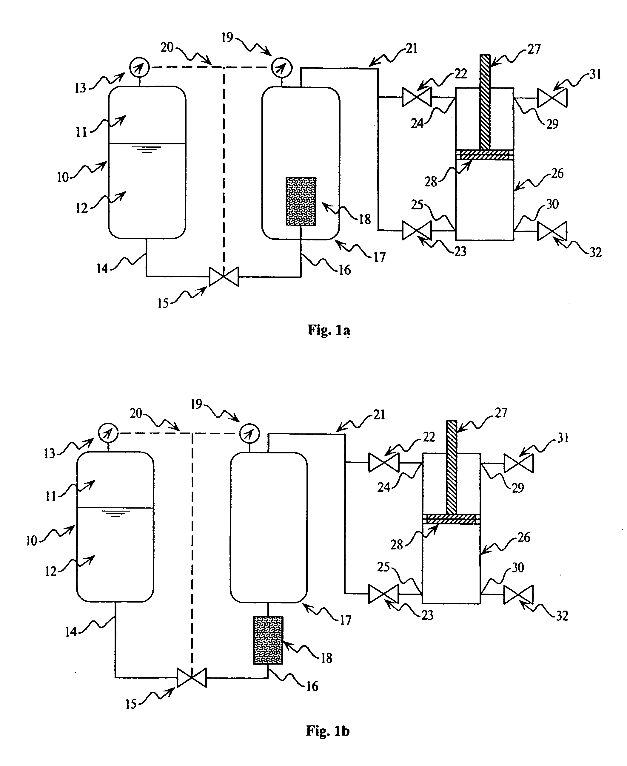
[0044]FIG. 1A illustrates a centralized monopropellant actuator embodiment. In this embodiment, the chemical energy of a monopropellant is released and stored in a central location and used to drive one or more pneumatic-type actuators. To this end, a blowdown fuel tank 10 is pre-pressurized with nitrogen or other inert gas 11 such that a monopropellant 12 is maintained at a sufficiently high pressure as measured by the pressure gage 13. The flow of monopropellant through a fuel line 14 is controlled by either a proportional or on / off liquid valve 15. Being driven by the higher pressure of the fuel tank 10, the monopropellant flows through line 14, through valve 15 (if it is open or partially open), and through line 16. Line 16 enters the pressure reservoir 17 where the monopropellant disassociates and expands into gaseous products within the catalyst pack 18. After disassociation, the gaseous products flow through the top of the screened surface...
second embodiment (figs.2a-2d)
[0048] Second Embodiment (FIGS. 2A-2D)
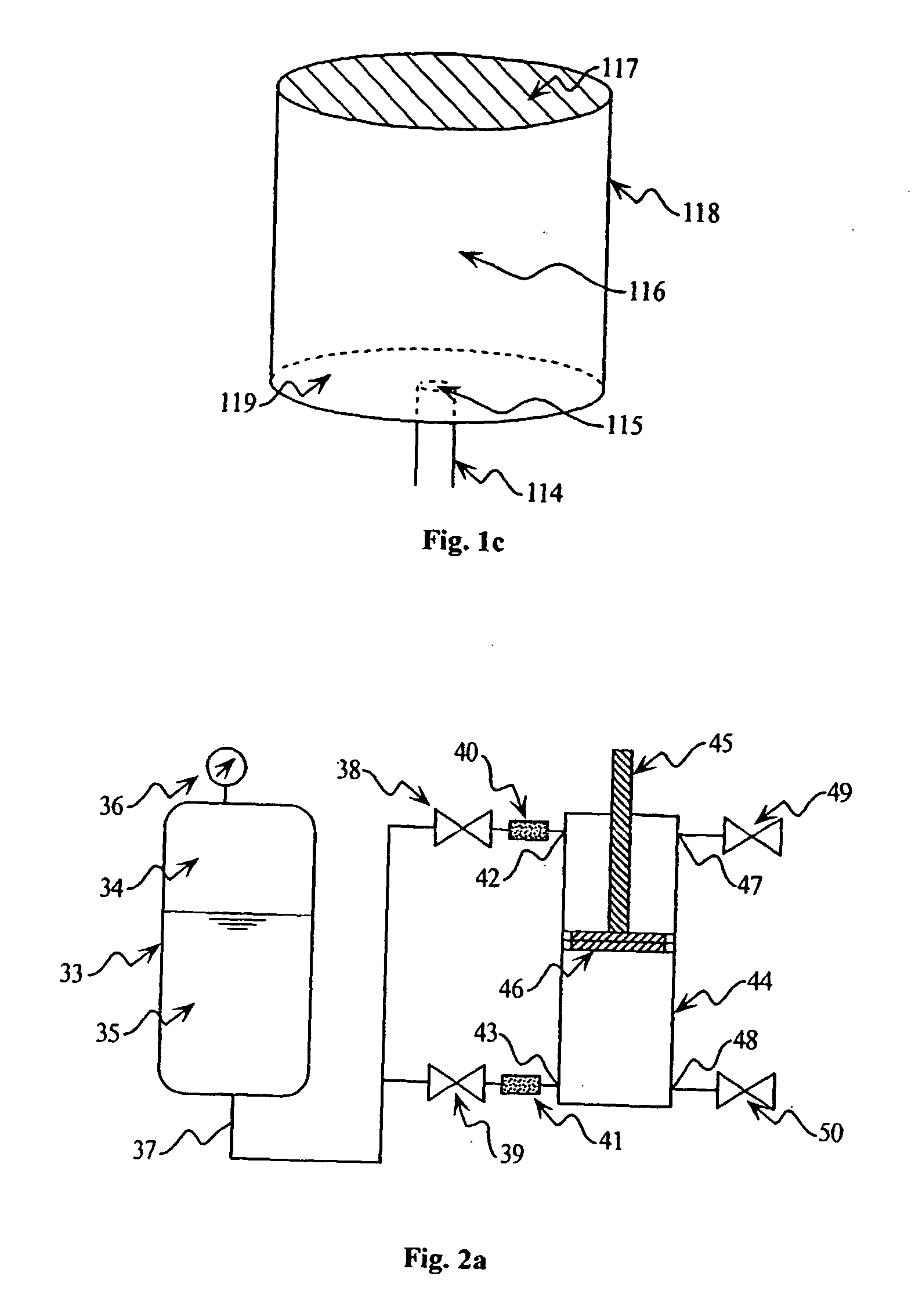
[0049]FIG. 2A illustrates a distributed monopropellant actuator embodiment. In this embodiment, the chemical energy of a monopropellant is distributed to one or more pneumatic-type actuators and released in a controlled manner inside the appropriate cylinder of the appropriate actuator. Shown in FIG. 2A is a blowdown fuel tank 33 pre-pressurized with an inert gas 34 and containing a monopropellant 35. This fuel tank 33 is instrumented with a pressure sensor 36 such that the pressure of the monopropellant liquid can be monitored. The liquid monopropellant is delivered via line or lines 37 to various pneumatic-type actuators (such as 44). Proportional valves 38 or 39 control the flow of monopropellant such that it flows through a catalyst pack 40 and / or 41. The catalyst packs contain catalytic agents such that the monopropellant may flow into, disassociate inside, and flow out of the pack without the catalytic agent being allowed to escape. The ga...
third embodiment (fig.3)
[0052] Third Embodiment (FIG. 3)
[0053]FIG. 3 illustrates a distributed hypergolic bipropellant powered actuator embodiment. In this embodiment, a liquid (or gaseous) fuel and a liquid (or gaseous) oxidizer constituting a hypergolic bipropellant mixture are delivered to one or more pneumatic-type actuators. The chemical energy of the fuel is released upon contact with the oxidizer locally within each actuator. With regard to a liquid fuel and liquid oxidizer, FIG. 3 illustrates one possible configuration of this embodiment. A blowdown fuel tank 51 is pre-pressurized with an inert gas 52 such that the fuel 53 is under pressure and is monitored by pressure sensor 54. A similar blowdown tank 56 contains a pre-pressurized inert gas 57 such that the oxidizer 58 is under pressure and is monitored by pressure sensor 59. Fuel and oxidizer is transported to a pneumatic-type actuator via lines 55 and 60 respectively. Proportional control valves 61 and 62 control the flow of fuel while proporti...
PUM
 Abstract
Description
Claims
Application Information
 - R&D
- Intellectual Property
- Life Sciences
- Materials
- Tech Scout
- Unparalleled Data Quality
- Higher Quality Content
- 60% Fewer Hallucinations
Browse by: Latest US Patents, China's latest patents, Technical Efficacy Thesaurus, Application Domain, Technology Topic, Popular Technical Reports.
© 2025 PatSnap. All rights reserved.Legal|Privacy policy|Modern Slavery Act Transparency Statement|Sitemap|About US| Contact US: help@patsnap.com


