Lightweight portable electric generator

a portable, electric generator technology, applied in the direction of machines/engines, magnetic circuit rotating parts, shape/form/construction, etc., can solve the problems of not showing good creep resistance, not showing full optimization and complete integration, and being bulky and heavy, so as to reduce weight, reduce speed fluctuations, and eliminate excess components

Inactive Publication Date: 2005-03-03
MAINSTREAM ENG
View PDF42 Cites 33 Cited by
  • Summary
  • Abstract
  • Description
  • Claims
  • Application Information

AI Technical Summary

Benefits of technology

[0012] To integrate the generator alternator into the engine flywheel to eliminate excessive components and reduce weight. The new flywheel alternator provides inertia to reduce speed fluctuations, provides a means of cooling both the electrical and mechanical components, and generates electrical power.
[0013] To provide an improved multi-function engine cowling, that not only provides protection from and to the rotating components, but also serves as a fan shroud, a fan scroll (or volute), a coolant distributor (to cool the engine, alternator, and engine oil), an electronic cold plate (for mounting and cooling rectification and / or voltage regulation electronics), and a coolant duct.

Problems solved by technology

However, it is typically bulky and heavy due to lack of weight optimization and integration.
This configuration provides a size and weight improvement over the first configuration, however, full optimization and complete integration is still lacking.
Of the magnesium alloys, magnesium-aluminum (AM) and magnesium-aluminum-zinc (AZ) alloys have excellent room temperature strength and / or ductility but do not exhibit good creep resistance.
AE alloys are expensive due to rare-earth additions, have poor die cast properties, have high oxidation rate, and low fatigue resistance.
However, the electric power generated by the alternator is small compared to the mechanical power generated by the shaft.
Those alternators are not designed to utilize all of the mechanical power generated by the engine shaft.
Finned structures common on existing flywheels alternators are not able to provide ample cooling to both the engine and the alternator.
Larger power generation creates larger quantities of waste heat that can not be removed by simple paddle style circulators.

Method used


Image

  • Lightweight portable electric generator
  • Lightweight portable electric generator
  • Lightweight portable electric generator

Examples


Embodiment Construction

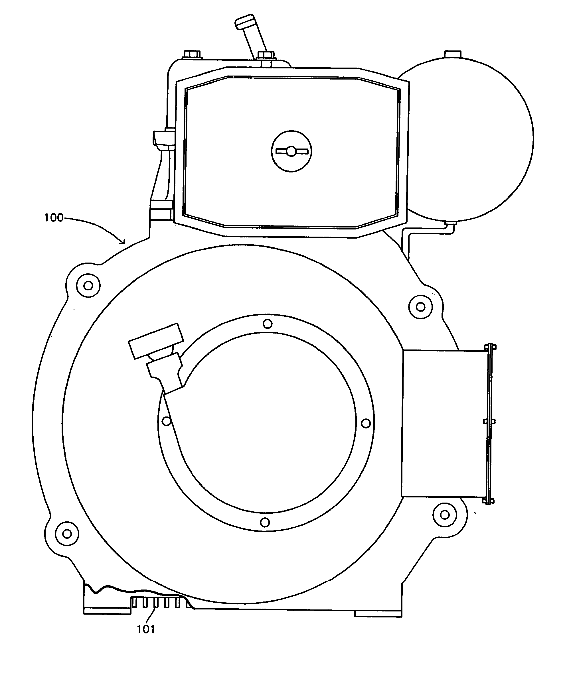
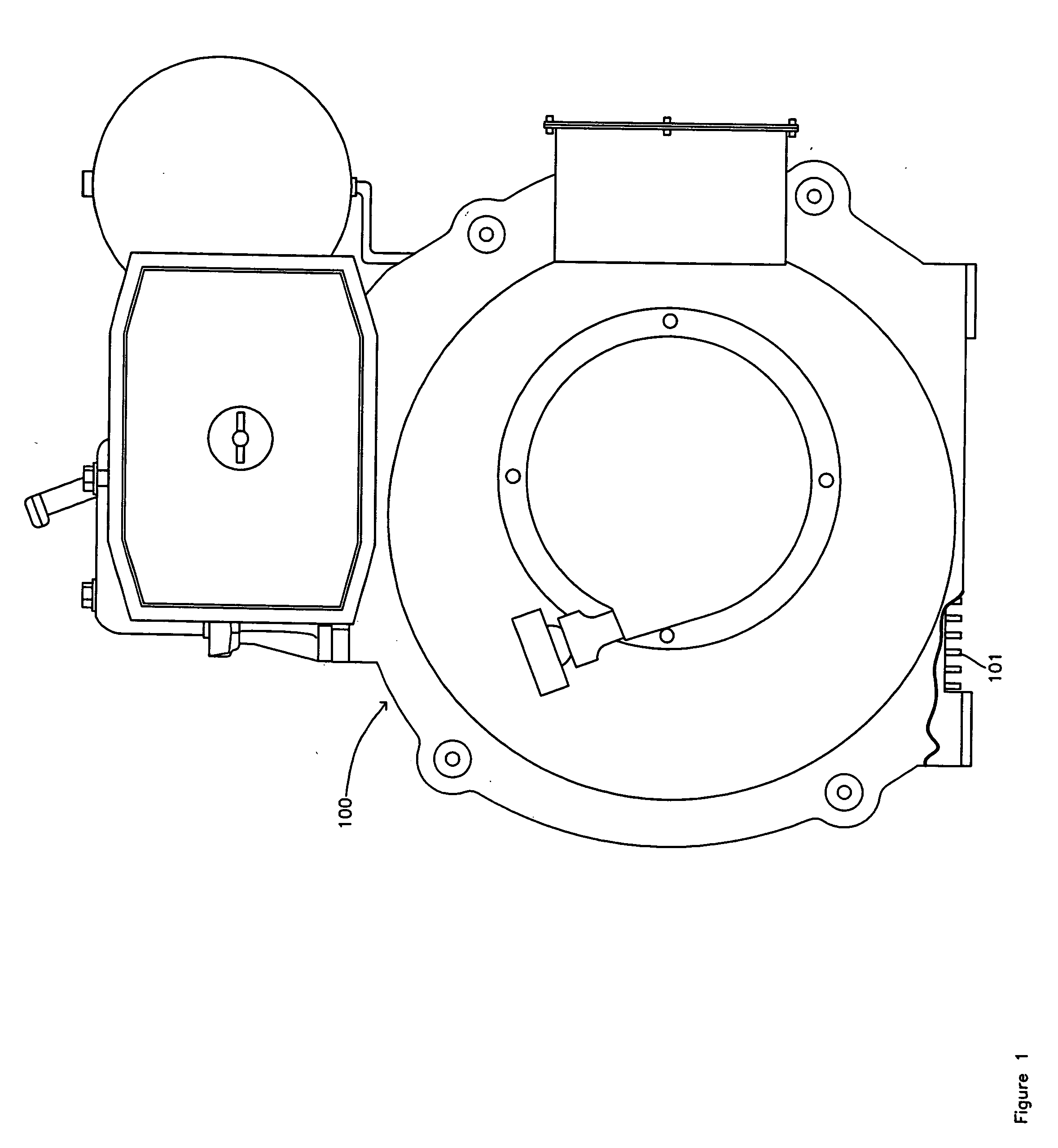
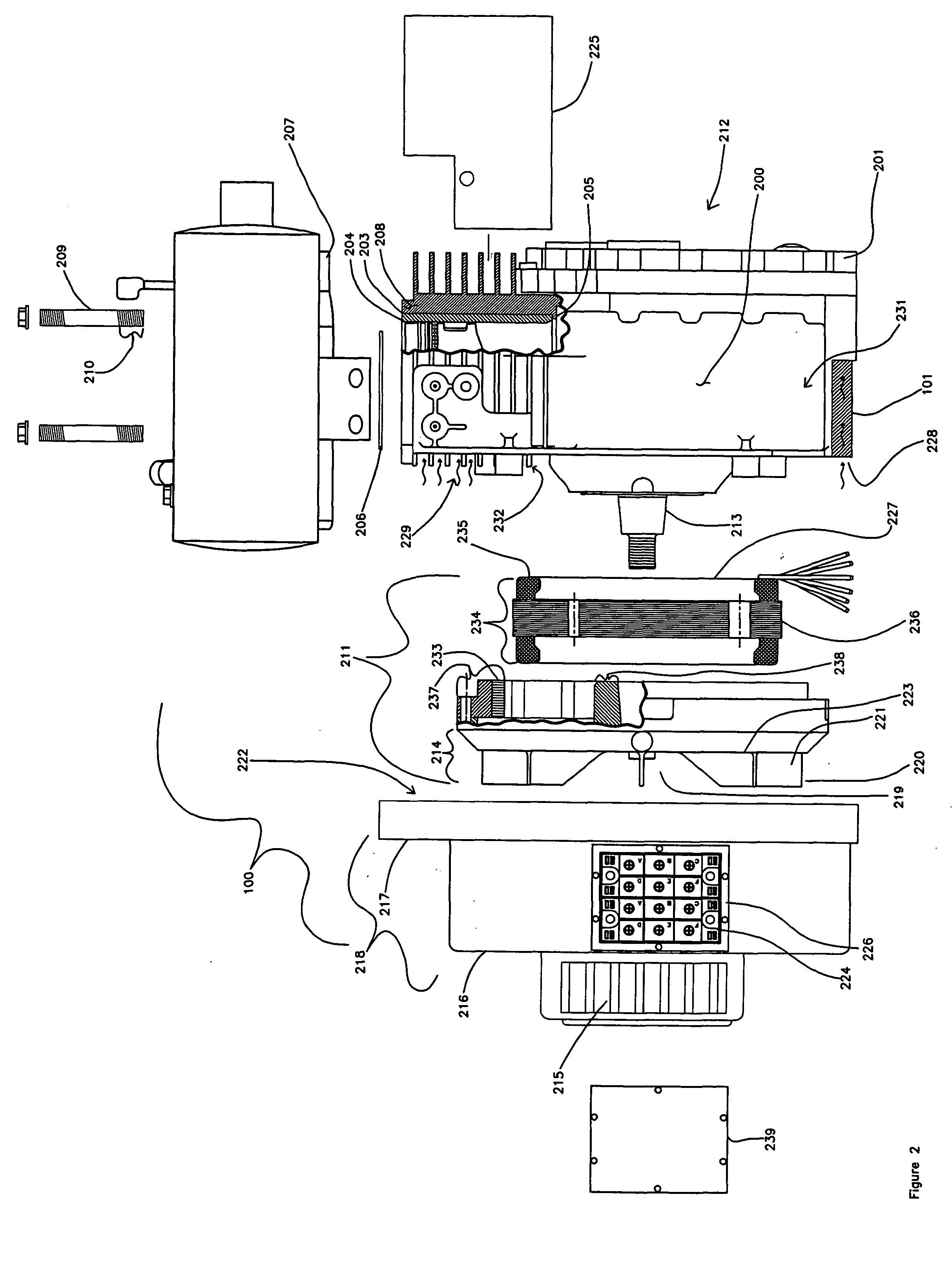
[0025] The present invention relates to air-cooled, portable electric power generation equipment. The internal combustion engine and the alternator are designed as an integrated unit and the alternator is the only driven mechanism of the engine. The internal combustion engine in the currently preferred embodiment is of the compression ignition type, although it will be apparent to anyone skilled in the art that the present invention also applies to spark ignition type engines. The following terms are defined to assist with the description of the invention as used the context of the present invention.

[0026] An internal combustion engine (or engine) is a device that generates mechanical power through the combustion of fuel. Compression-ignition engines and spark-ignition engines are types of engines.

[0027] An alternator is a device that converts mechanical power into alternating electrical power through the use of electromagnetic fields. Permanent magnet alternators are a type of al...


PUM


Abstract

A compact and lightweight electric generator for portable power applications employs a new engine design and integration approach for reducing engine and generator weight. A unique flywheel alternator generates electrical power and provides inertia for the engine, pressurized air for cooling, and inertia for the alternator. An engine cowling provides rotating component protection, a fan shroud mechanism, cooling air ducts, and a cooling mechanism for handling large quantities of heat produced by rectified power conversion.

Description

BACKGROUND OF THE INVENTION [0001] 1. Field of the Invention [0002] The present invention relates to electrical generators, particularly, to size and weight improvements of air-cooled, portable electric generators. A flywheel alternator mounted on an air-cooled internal combustion engine generates electrical power. Improvements in the engine design and the functionality of the integrated flywheel alternator result in a smaller and lighter generator that is easier to transport. [0003] 2. Description of the Related Art [0004] Air-cooled, portable electric generators of the prior art are typically comprised of an air-cooled internal combustion engine coupled mechanically through a power takeoff shaft to an alternator. The power takeoff shaft is typically integral to the crankshaft on the side of the engine opposed to the engine flywheel, although power takeoff shafts integral to the camshaft on a side of the engine opposed to the engine flywheel are also common. The flywheel provides a...

Claims


Application Information

Patent Timeline
Patent Type & Authority Applications(United States)
IPC IPC(8): F01M11/00F01P1/02F01P1/06F02B63/04H02K1/27H02K7/18H02K9/06H02K11/04
CPCF01M11/0004F01P1/02F01P1/06F02B63/04H02K11/046H02K1/2786H02K7/1815H02K9/06F05C2201/028H02K11/05H02K1/2791
Inventor COLE, GREGORYTEWS, BRIANSCARINGE, ROBERTDAVIS, RUSSELL
Owner MAINSTREAM ENG
Why Eureka
Try Eureka