Electromagnetic valve system

a technology of electromagnetic valves and valve bodies, applied in the direction of non-mechanical valves, magnetic bodies, machines/engines, etc., can solve the problems of requiring more than one crankshaft revolution to make the change, poor drivability, and slow disassembly and assembly, etc., to achieve easy movement between positions, increase or decrease the local magnetic flux, and promote the effect of valve movemen

Inactive Publication Date: 2005-03-03
SOCIAL PROFIT NETWORK
View PDF8 Cites 40 Cited by
  • Summary
  • Abstract
  • Description
  • Claims
  • Application Information

AI Technical Summary

Benefits of technology

[0022] Systems are provided for electromagnetic actuation of a valve mechanism. A valve is linearly moveable between a first closed position and a second open position. A first spring is compressed when the valve is in the first closed position, and a second valve spring is compressed when the valve is in the second open position. An electromagnetic actuation assembly and a permanent magnet is combined with the valve, such that the valve is latchable in either a closed or open position, and is readily movable between positions through application of en

Problems solved by technology

This approach has had limited success in practice because the usual control activates or deactivates half the number of cylinders, and this abrupt change in output torque causes poor drivability.
Furthermore, the disabling mechanism is relatively slow acting, so that more than one revolution of the crankshaft is required to make the change.
While some electromagnetic valve mechanisms have been implemented to operate valves, the energy required to operate the system is typically

Method used


Image

  • Electromagnetic valve system
  • Electromagnetic valve system
  • Electromagnetic valve system

Examples


Embodiment Construction

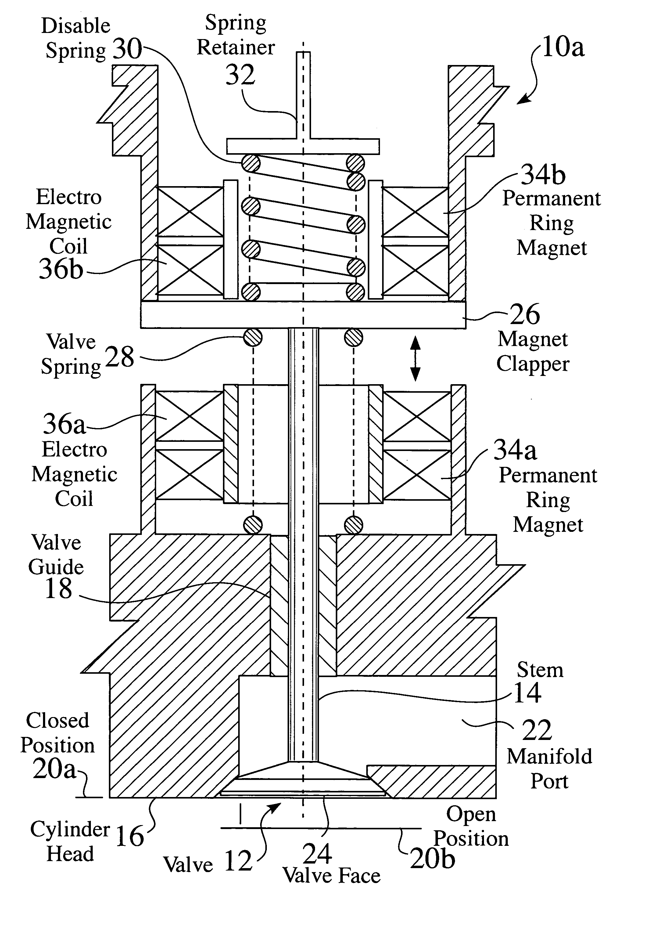
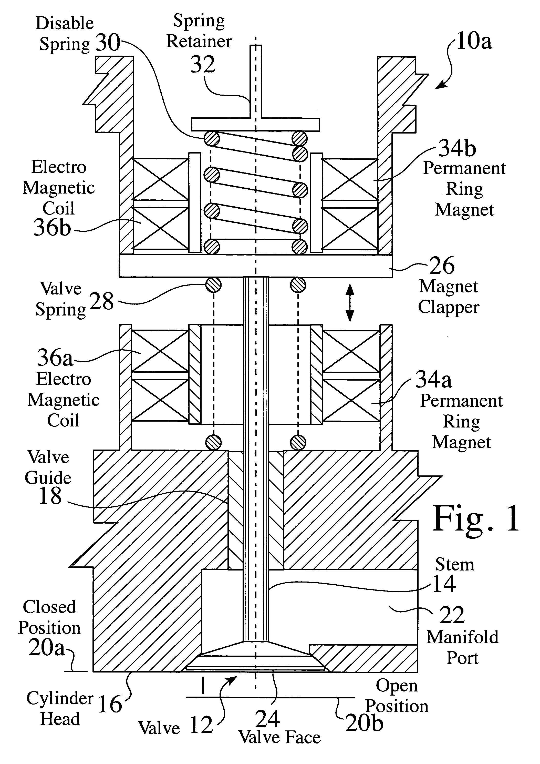
[0078]FIG. 1 is a partial cross sectional view of an electromagnetic valve system 10a. A valve 12, having a stem 14, is linearly moveable within a cylinder head 16, such as through a valve guide 18. The valve 12 is linearly moveable between a closed position 20a and an open position 20b, to allow flow into or out of a manifold port 22.

[0079] The valve 12 comprises a valve face 24 at one end of the stem 14. A clapper 26 is affixed to the stem 14, such that movement of the clapper results in movement of the valve 12. A valve spring 28 is located between the head 16 and the clapper 26, which biases the valve 12 toward a closed position 20a. A disable spring 30 is located on an opposing surface of the clapper 26, to bias the valve 12 toward an open position 20b. The disable spring 30 is typically affixed in relation to the cylinder head 16, such as by a retainer32.

[0080] A first permanent magnet 34a and first electromagnet 36a are located on one side of the clapper 26, and a second pe...


PUM


Abstract

Systems are provided for electromagnetic actuation of a valve mechanism. A valve is linearly moveable between a first closed position and a second open position. A first spring is compressed when the valve is in the first closed position, and a second valve spring is compressed when the valve is in the second open position. An electromagnetic actuation assembly and a permanent magnet is combined with the valve, such that the valve is latchable in either a closed or open position, and is readily movable between positions through application of energy to the electromagnetic circuitry. The electromagnetic circuitry is controllable to increase or decrease the local magnetic flux, such as to promote movement of the valve, or to provide a soft landing of the valve at either end of movement. Some system embodiments provide energy recovery, feed back, and/or feed forward sensing and control. The electromagnetic valve system can be implemented for a wide variety of engines, valves and actuators, such as for variable valve timing, valve disablement, and/or hybrid engine and energy storage applications.

Description

CROSS-REFERENCE TO RELATED APPLICATIONS [0001] This application claims priority to U.S. Provisional Patent Application No. 60 / 490,195, filed 25 Jul. 2003, which is incorporated herein by reference. [0002] This application is also a Continuation in Part of U.S. application Ser. No. 10 / 674,743, filed 29 Sep. 2003, which claims priority to U.S. Provisional Patent Application No. 60 / 417,264, filed 9 Oct. 2002, which is incorporated herein by reference.FIELD OF THE INVENTION [0003] The invention relates to the field of internal combustion engines. More particularly, the invention relates to a structure and process for the controlled movement, latching and / or disablement valves. BACKGROUND OF THE INVENTION [0004] The poppet valve driven by a camshaft has bee used in internal combustion engines for many years. Modifications to the valve train have been developed to permit changing the valve timing while the engine is in operation. When the timing control prevents the valves from opening du...

Claims


Application Information

Patent Timeline
IPC IPC(8): F01L9/20F01LF01L1/34F02BF16K11/04F16K31/06F16K31/08H01F3/00
CPCF01L9/04F01L2009/0448F16K31/082F16K31/0689F16K31/0679F01L2009/2148F01L9/20
Inventor MOYER, DAVIDMOYER, PATRICIA M.SCHWARTZ, GEORGEMORRISON, KEVIN
Owner SOCIAL PROFIT NETWORK
Why Eureka
Try Eureka