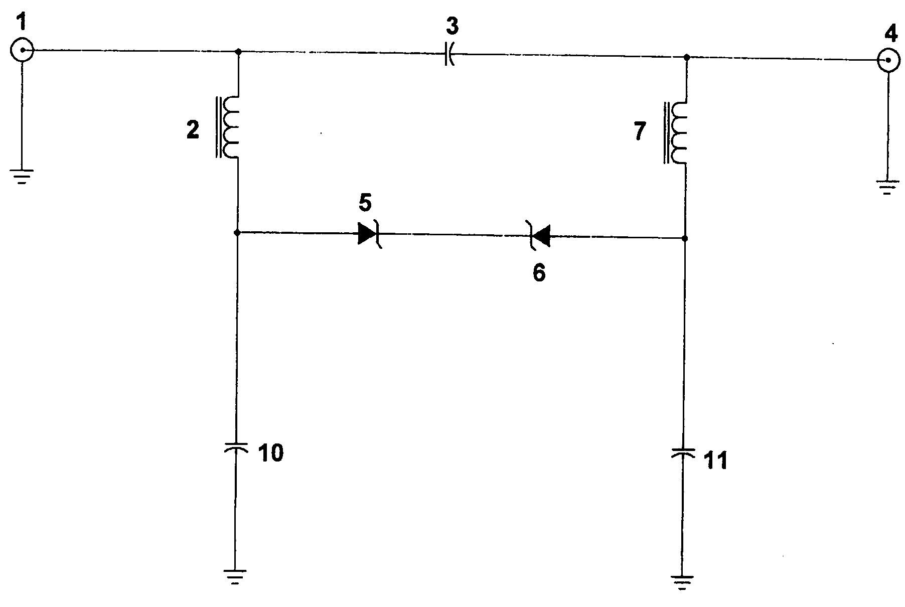
Voltage limiter for coaxial cable carrying RF signals and voltage

Inactive Publication Date: 2005-03-03
EAGLE COMTRONICS
View PDF8 Cites 55 Cited by
  • Summary
  • Abstract
  • Description
  • Claims
  • Application Information

AI Technical Summary

Benefits of technology

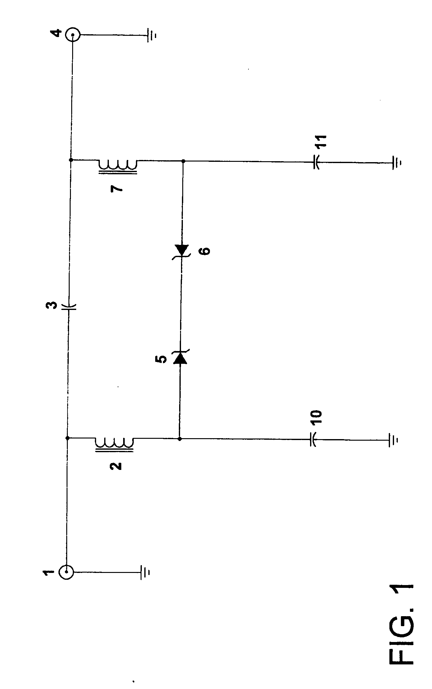
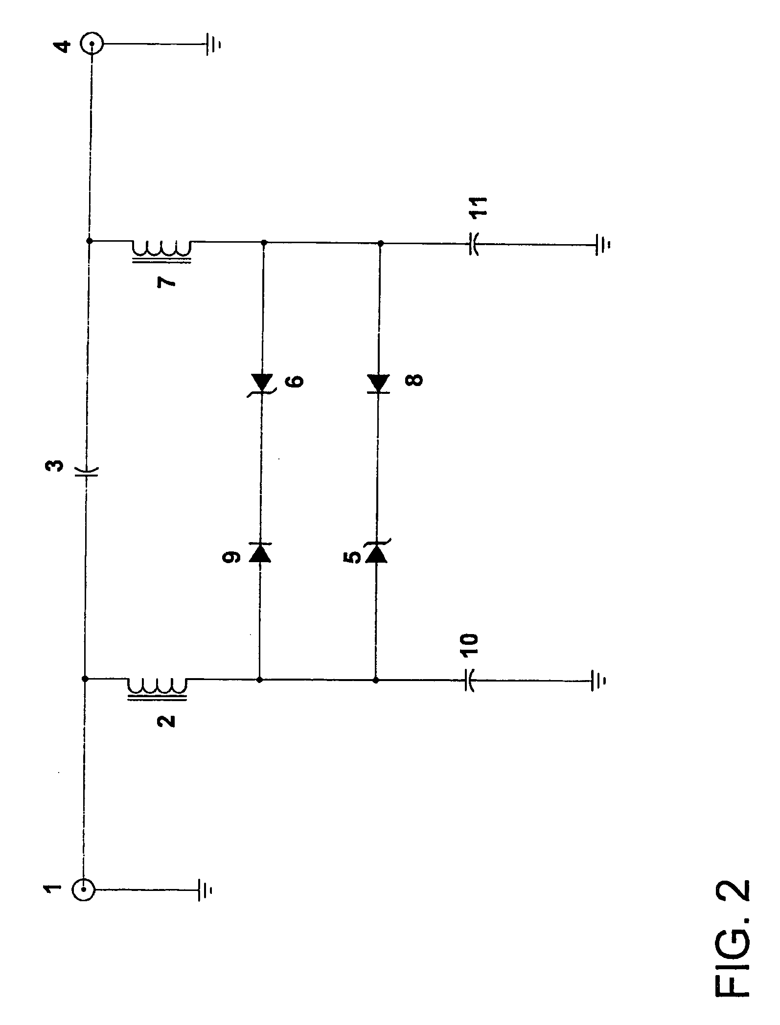
[0030] The voltage limiter according to the present invention solves all the problems associated with the prior art devices described above. First, rather than relying upon a complex current interrupt-type system, the present invention transforms the 90 volt AC powering voltage signal into a 60 volt AC powering voltage signal, which allows the CATV provider to operate under the regulations of NEC 820, rather than the more burdensome requirements of NEC 830.
[0031] The voltage limiter according to the present invention is also much more reliable in the field, in that it can be provided within a single, sealed housing, such as an Eagle Comtronics EM or 10M sized tubular package. Being a one-piece unit, the voltage limiter is also easy to install, in that it can be attached directly to the output port of a directional tap connected to a main line distribution cable.
[0032] The voltage limiter of the present invention is highly efficient, even in vi

Problems solved by technology

The voltage supplied to the main line distribution cable is subject to a series of voltage drops associated with each active and passive device carried by the main line distribution cable, and by the series resistance of the main line cable itself, connected between the active and passive devices, which ultimately limits the number of devices that can be powered effectively from a single power supply unit.
Since each active device within the distribution system consumes a certain amount of power, the voltage available for subsequent active devices drops due to the voltage drop associated with each successive active device.
This new voltage level, however, exceeds the limits for drop cables set by the National Electric Code (NEC) and the energy limitations stated in Section 820-4 of Community Antenna Television and Radio Distribution Systems, Article 820.
The more stringent standards of NEC 830 result in a significant increase in hardwar

Method used


Image

  • Voltage limiter for coaxial cable carrying RF signals and voltage
  • Voltage limiter for coaxial cable carrying RF signals and voltage
  • Voltage limiter for coaxial cable carrying RF signals and voltage

Examples


Embodiment Construction

[0039] The voltage limiter of the present invention operates in connection with the particular waveform characteristics of the 60 Hz AC signal provided by the CATV power supply. That is, the typical CATV power supply includes a Ferro-resonate circuit having an output that is substantially a square wave (e.g., quasi-square wave) or a sharp transient trapezoidal wave. These types of waveforms offer a higher level of efficiency when compared with the standard sine wave AC signal typically associated with household electrical outlets. Further, the quasi-square or sharp transient trapezoidal waveforms still provide an alternating current that discourages galvanic reactions (interactions) between dissimilar metals found within the distribution line.

[0040] As it is commonly known in the art, the flat tops (as apposed to sharp or rounded peaks) of the quasi-square and trapezoidal AC waveform types provide a longer conduction period (phase) for rectifier circuits within the power supply sys...


PUM


Abstract

A voltage limiter for a coaxial cable line that carries an RF signal and an AC powering voltage signal is provided, including a signal input carrying a first AC voltage signal and an RF signal, a signal output arranged in series with the input and carrying the RF signal and a second AC voltage signal that is lower than the first AC voltage signal, and a voltage limiting mechanism arranged between the input and the output. The voltage limiting mechanism reduces the first AC voltage signal to the second AC voltage signal without substantially affecting the integrity of the RF signal.

Description

CROSS-REFERENCE TO RELATED APPLICATION [0001] This application is a non-provisional of U.S. Application Ser. No. 60 / 497,871, filed Aug. 26, 2003, the entirety of which is incorporated herein by reference.FIELD OF THE INVENTION [0002] The present invention relates to a voltage limiter for a coaxial cable that carries RF signals and voltage, and in particular relates to a voltage limiter that reduces the amplitude of the voltage carried on a drop cable extending from a main line distribution cable to a lower level that can be safely carried by the drop cable to a subscriber residence. BACKGROUND OF THE INVENTION [0003] CATV distribution systems typically include active devices and passive devices that are physically connected via main line distribution cables that have a metallic center conductor provided within a metallic sheath and surrounded by an insulator. Examples of the active devices typically included in a main line distribution cable of a CATV distribution system include amp...

Claims


Application Information

Patent Timeline
IPC IPC(8): H02H9/00H02H9/04H02H9/06H04H1/00H04H20/78H04N7/10
CPCH04H20/78H02H9/005
Inventor MARLAND, DALE W.
Owner EAGLE COMTRONICS
Why Eureka
Try Eureka