Motor speed control device

a control device and motor technology, applied in the direction of process and machine control, electronic commutators, instruments, etc., can solve the problems of wasting power, reducing the life of fans, generating unnecessary noise, etc., and achieves the effect of simple external circuit and easy control of temperature turning points

Inactive Publication Date: 2005-03-03
DELTA ELECTRONICS INC
View PDF13 Cites 38 Cited by
  • Summary
  • Abstract
  • Description
  • Claims
  • Application Information

AI Technical Summary

Benefits of technology

[0006] An object of the present invention is to provide a motor speed control device applied to a fan for controlling its rotation speed in different temperature ranges by a thermistor and a simple external circuit, easily controlling turning points of temperature when the fan functions at a relatively low speed.

Problems solved by technology

However, under light loading, fans generally continue to operate at full speed, wasting power, generating unnecessary noise, and reducing fan life.
The transistor consumes much power and generates heat accordingly.
Also, when power consumption is too high or input voltage from the power source is too low, the thermistor RTH cannot function normally, thereby generating excess heat and increasing the inner temperature of the computer system.

Method used


Image

  • Motor speed control device
  • Motor speed control device
  • Motor speed control device

Examples


first embodiment

[0023] First Embodiment

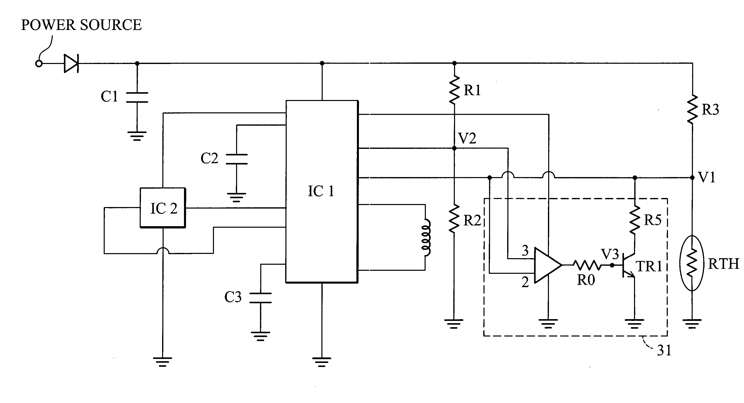
[0024]FIG. 3A is a schematic diagram of the first embodiment of the motor speed control device of the present invention. As shown in FIG. 3, a power source supplies voltage to start fan rotation by inter-induction between winding coils and magnetic rings of the motor. A Hall induction integration circuit IC2 detects electric waves induced by magnetic field variation between winding coils and magnetic rings of the fan. After, the Hall induction IC IC2 outputs two positive and negative voltages to a driving integration circuit IC1. Thus, the circuit IC1 and the circuit IC2 constitute a driving element to drive the fan and send a feedback periodic pulse signal.

[0025] As well, the driving element is connected to a thermal sensor (or a thermistor) RTH and a switch circuit, wherein the switch circuit 31 includes a comparator, a transistor TR1, and two resistors R0 and R5 (as indicated by the dotted line in FIG. 3A). The thermal sensor RTH has various resistances at...

second embodiment

[0027] Second Embodiment

[0028]FIG. 4A is a schematic diagram of the second embodiment of the motor speed control device of the present invention. As shown in FIG. 4A, the detailed circuit and control theory are similar to those in the first embodiment. The difference between these two embodiments lies in a resistor R4 electrically connected with the thermal sensor RTH in series in this embodiment, unlike the switch circuit of the first embodiment.

[0029]FIG. 4B plots variation between the temperature and rotation speed in the second embodiment of the motor speed control device of the present invention. FIG. 4B shows variations in the slope between temperature and rotation speed of the fan before and after the resistor R4 is connected with the thermal sensor RTH in series. Without the resistor R4, the slope from temperature T1 to T2 is A. After the resistor R4 is connected with the thermal sensor RTH in series, variation of the first voltage V1 decreases. Temperature range from T2 to...

third embodiment

[0030] Third Embodiment

[0031]FIG. 5A is a schematic diagram of the third embodiment of the motor speed control device of the present invention. As shown in FIG. 5A, the detailed circuit and control theory are similar to those in the first embodiment. The difference between these two embodiments lies in a subtraction circuit 51 of this embodiment replacing the switch circuit of the first embodiment. The subtraction circuit 51 includes a comparator and six resistors R6, R7, R8, R9, R10, and R11, as indicated by the dotted line in FIG. 5A.

[0032]FIG. 5B plots variation between the temperature and rotation speed in the third embodiment of the motor speed control device of the present invention. As shown in FIG. 5B, when resistances of the resistors R6, R7, R8, and R11 are equal, voltage V5 equals voltage of voltage V4 taken away from voltage V1. Temperature range of the fan at full speed is thus reduced by adjusting fourth voltage V4, whereby the slope changes from A to a larger value D...


PUM


Abstract

A motor speed control device. The motor speed control device applied to a direct current (DC) fan includes a driving element constituted by a driving IC and Hall IC, a thermal sensor and a control element electrically connected between the driving element and the thermal sensor. The present invention utilizes a thermal sensor and a simple control element to effectively and stably control the variable speed of the fan within different temperature ranges.

Description

BACKGROUND OF THE INVENTION [0001] 1. Field of the Invention [0002] The present invention relates to a motor speed control device, and in particular to a motor speed control device applied to a direct current (DC) fan. [0003] 2. Description of the Related Art [0004] Traditionally, when electronic devices function under heavy load, cooling fans operate at full speed. However, under light loading, fans generally continue to operate at full speed, wasting power, generating unnecessary noise, and reducing fan life. Accordingly, a method to control the rotation speed of the fan has been developed. As shown in FIG. 1, when an electronic device functions under light loading, its inner temperature remains low. A thermistor RTH detects the temperature variation, adjusts its resistance accordingly, adjusts voltage and current from the power source, and outputs a signal to a driving circuit IC, which outputs a pulse width modulation (PWM) to a transistor TR, the switch frequency of which varie...

Claims


Application Information

Patent Timeline
Patent Type & Authority Applications(United States)
IPC IPC(8): H02P6/06H02P6/08H02P6/16H02P6/17H02P6/26H05K7/20
CPCH05K7/20209
Inventor LIU, CHENG-CHIEHHUANG, YAO-LUNGTSAI, MING-SHIHUANG, WEN-SHI
Owner DELTA ELECTRONICS INC
Why Eureka
Try Eureka