

Organic electroluminescent device based upon emission of exciplexes or electroplexes, and a method for its fabrication
a technology of exciplexes and electroplexes, applied in the direction of luminescnet screens, discharge tubes, natural mineral layered products, etc., can solve the problems of reducing efficiency and damage to the device, and achieve the effect of easy and inexpensive manufacturing
- Summary
- Abstract
- Description
- Claims
- Application Information
AI Technical Summary
Benefits of technology
Problems solved by technology
Method used
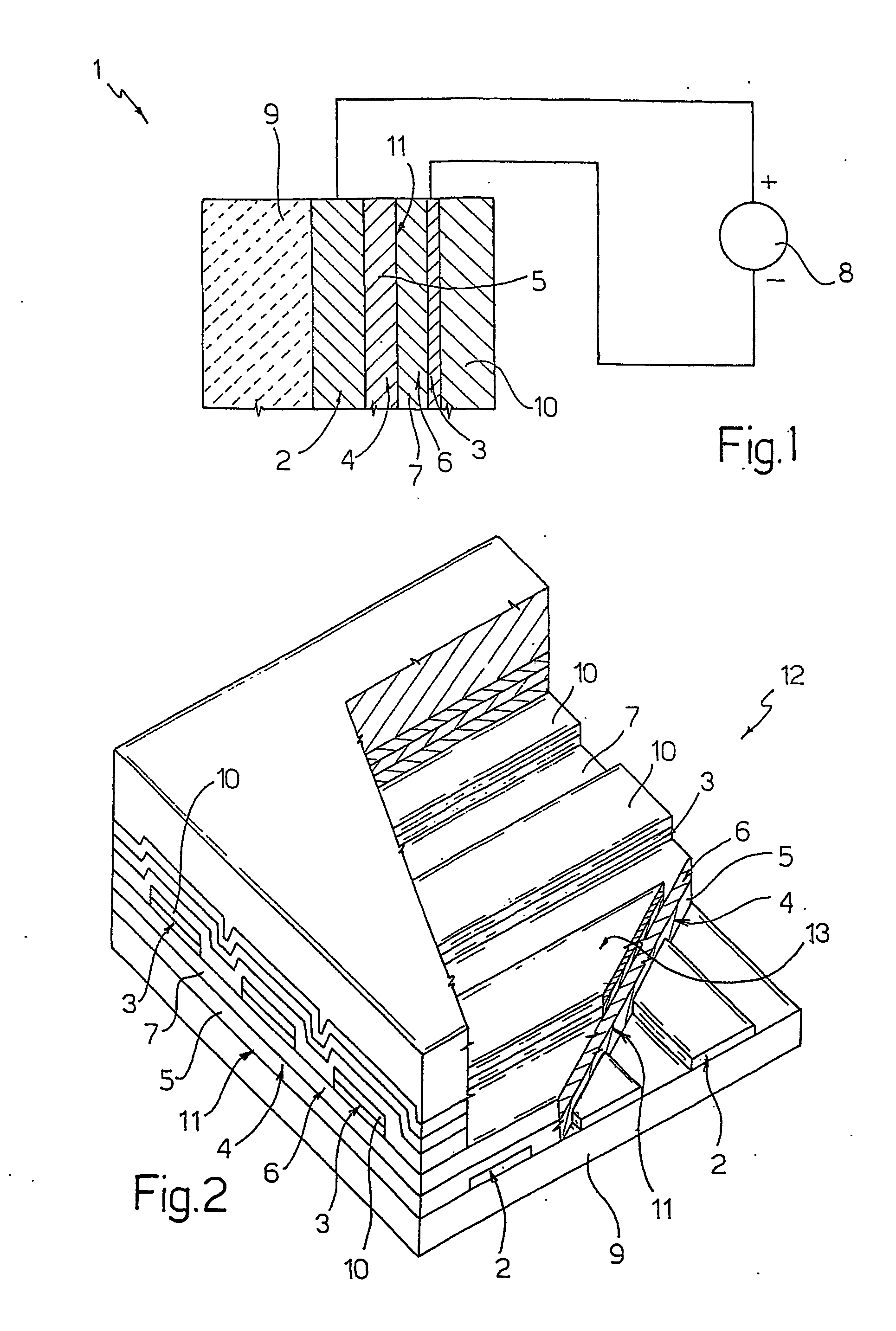
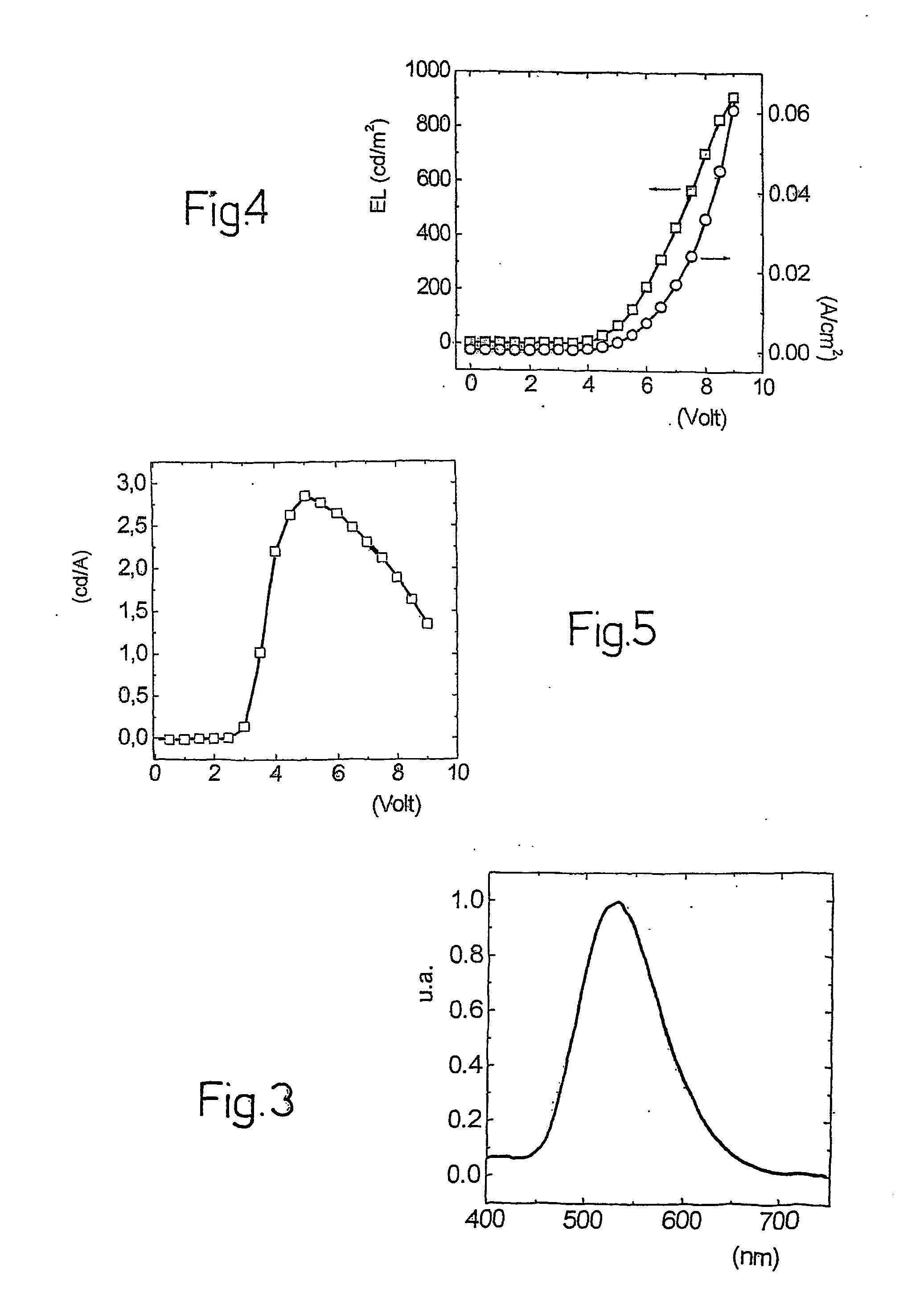
Image

Examples
example 1
An organic electroluminescent device was prepared in the following way.
A plate of glass coated with a layer of indium and tin oxide, which has a thickness of approximately 100 nm and is substantially transparent, was cleaned by being dipped in a boiling solution of acetone and alcohol and subsequently being put into an ultrasound washer for approximately thirty minutes.
At this point, the following layers were deposited, in succession, one on top of the other, by sublimation in an high-vacuum evaporator and at a pressure of 8×10□4 Pa, on the coated glass plate: a layer of 4,4′,4″-tri(N,N-diphenyl-amino)-triphenylamine (TDATA) of a thickness of 60 nm; a layer of a thickness of 60 nm of 3-(4-diphenylyl)-4-phenyl-5-ter-butylphenyl-1,2,4-triazole (PBD); a layer of calcium of a thickness of 25 nm; and a layer of silver of a thickness of 100 nm.
Note that the ionization potential and the electronic affinity of TDATA are substantially between 5 eV and 5.1 eV and 1.5 eV and 1.9 eV, res...
example 2
An organic electroluminescent device was prepared in a substantially identical way as the organic electroluminescent device of Example 1, except for the fact that, instead of the layer of TDATA, a layer of 4,4′,4″-tri(carbazol-9-yl)-triphenylamine (TCTA) was deposited.
Note that the ionization potential and the electronic affinity of TCTA are approximately equal to 5.6 eV and 2.3-1.9 eV, respectively. The ionization potential and the electronic affinity of PBD are approximately 6.3 eV and 2.8 eV, respectively. Consequently, in absolute value, the differences between the potentials of ionization and between the electronic affinities of TCTA and PBD are approximately 0.7 eV and 0.5 eV, respectively.
The device thus obtained, which has an active surface of 0.07 cm2, was tested under laboratory conditions (i.e., with a temperature of between 20° C. and 24° C. and with a humidity of between 55% and 65%) and revealed an electromagnetic emission in the blue-violet.
example 3
An organic electroluminescent device was prepared in a substantially identical way as the organic electroluminescent device of Example 2 except for the fact that, instead of the layer of TCTA, there was deposited a layer of 4,4′,4″-tri(N-3-methylphenyl-N-phenyl-amino)-triphenylamine (M-TDATA). Note that the ionization potential and the electronic affinity of M-IDATA are substantially between 5 eV and 5.1 eV and 1.5 eV and 1.9 eV, respectively. The ionization potential and the electronic affinity of PBD are approximately 6.3 eV and. 2.8 eV, respectively.
Consequently, in absolute value, the differences between the potentials of ionization and between the electronic affinities of M-TDATA and of PBD are approximately 1.2 eV and 1.1 eV, respectively.
The device thus obtained, which has an active surface of 0.07 cm2, was tested under laboratory conditions (i.e., with a temperature of between 20° C. and 24° C. and with a humidity of between 55% and 65%) and revealed an electromagnetic ...
PUM
| Property | Measurement | Unit |
|---|---|---|
| ionization potential | aaaaa | aaaaa |
| transparent | aaaaa | aaaaa |
| ionization potential | aaaaa | aaaaa |
Abstract
Description
Claims
Application Information