Optical head

a technology of optical head and optical head, which is applied in the field of optical head, can solve the problems of reducing the power of laser beam, arithmetic circuit malfunction, and reducing the calorific value of laser beam, so as to achieve effective dissipation, reduce the area of heatsink, and high dissipation efficiency

Inactive Publication Date: 2005-03-03
PANASONIC CORP
View PDF7 Cites 17 Cited by
  • Summary
  • Abstract
  • Description
  • Claims
  • Application Information

AI Technical Summary

Benefits of technology

[0016] The heat dissipating medium is preferably ferrofluid. This prevents the actuator motion of the movable part from being interfered with and allows unnecessary vibration of the movable part to be absorbed.
[0017] The movable part further comprises a heatsink. Therefore, Joule heat generated in the light emitting element and the light receiving element can be more effectively dissipated. Furthermore, since heat of the movable part can effectively be dissipated through the heat dissipating medium, the area of the heatsink can be reduced as compared with the conventional optical head. Therefore, the actuator motion of the movable part is not interfered with in spite of the achievement of a high dissipating efficiency.
[0018] The optical head further comprises: a yoke provided as a part of the fixed part; a coil wound around the yoke; and a magnet contacting the heatsink and spaced apart from the coil, wherein the h...

Problems solved by technology

As a result, power consumption in light emitting elements and light receiving elements has drastically been increasing and thus calorific value has drastically been increasing...

Method used


Image

  • Optical head
  • Optical head
  • Optical head

Examples


embodiment 1

[0032] (Embodiment 1)

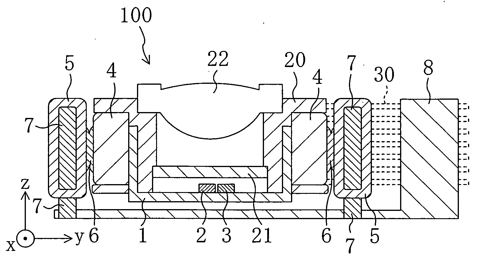
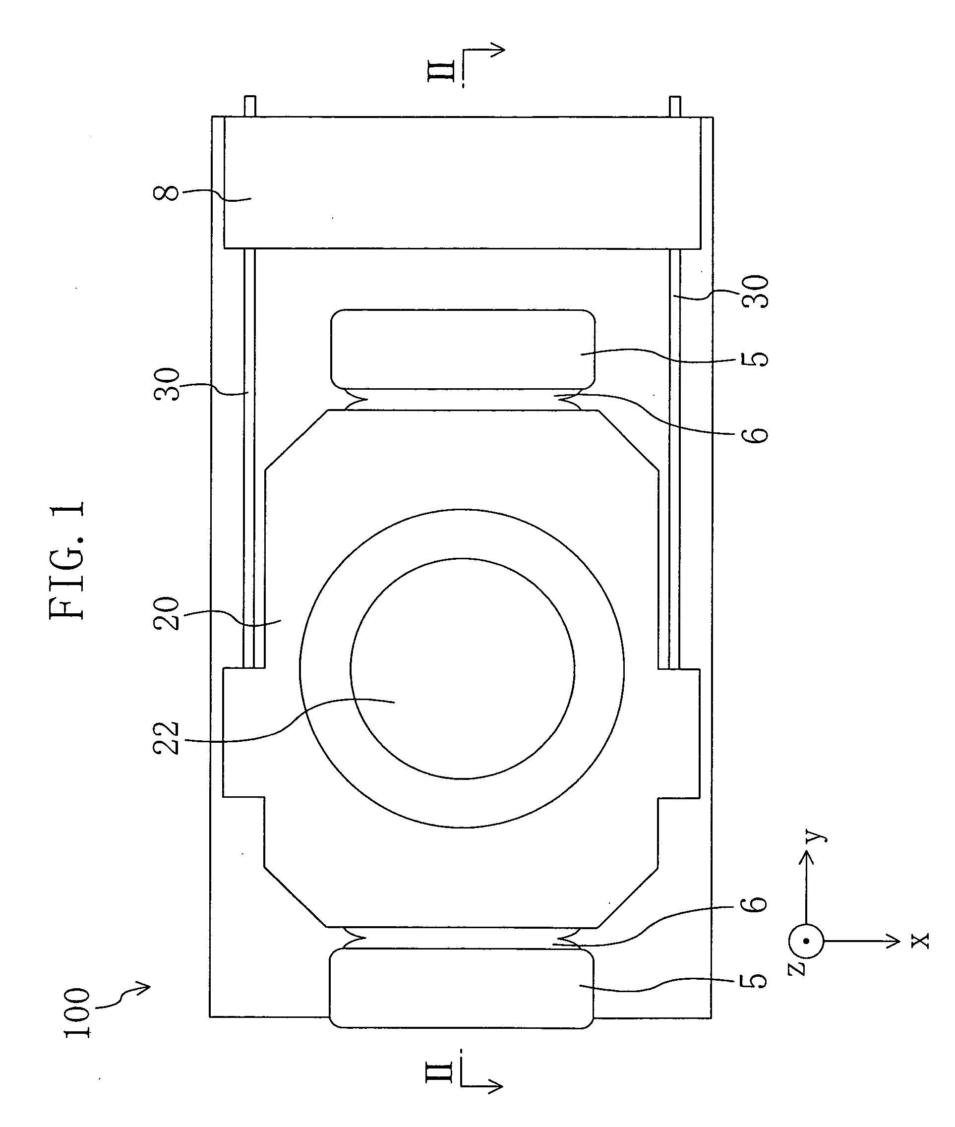
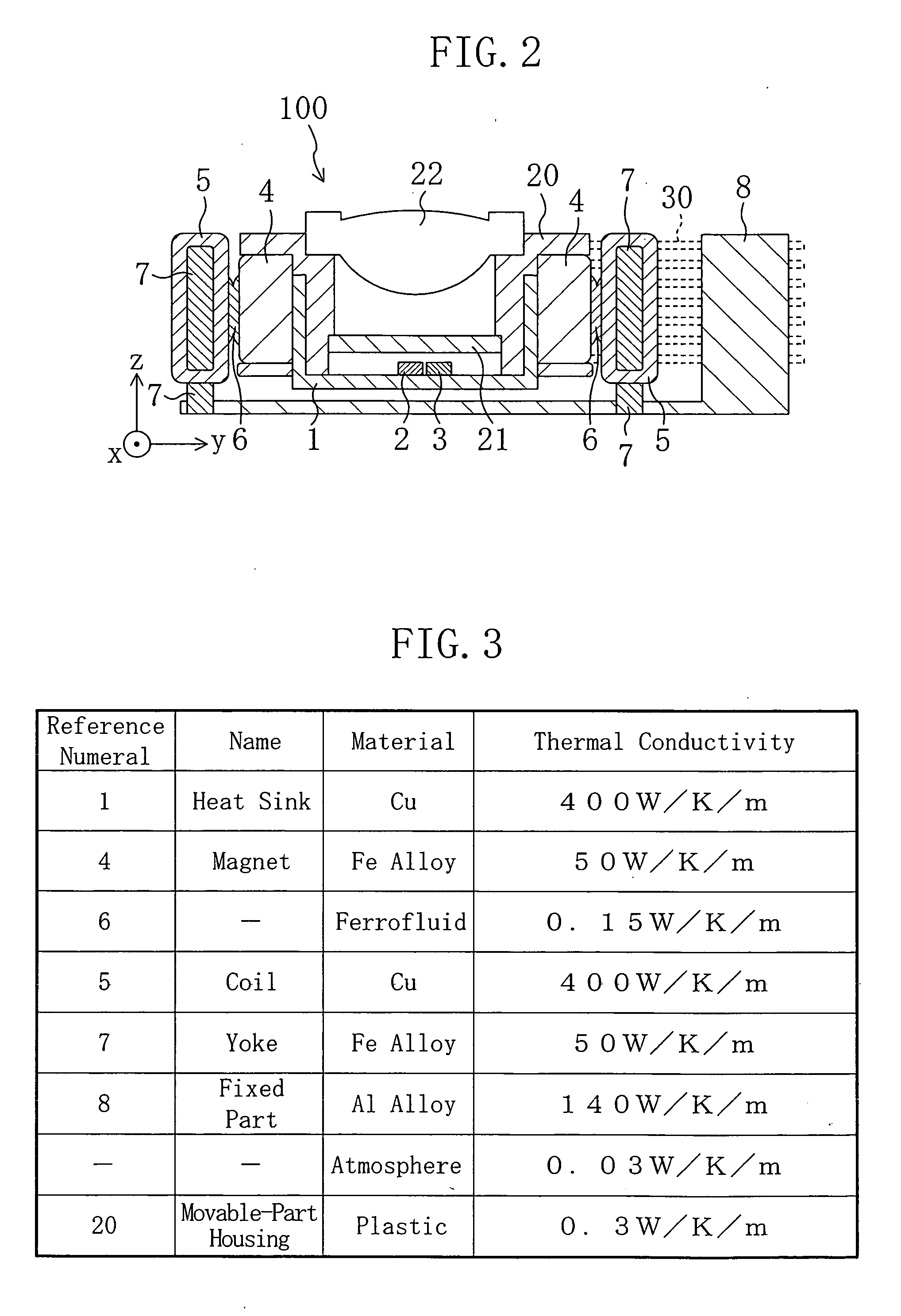
[0033]FIG. 1 is a plan view showing an optical head according to a first embodiment of the present invention when viewed from above. FIG. 2 is a cross sectional view of the optical head according to the first embodiment taken along the line II-II shown in FIG. 1. In FIG. 2, the x direction means the depth direction of the paper, the y direction means a side-to-side direction, i.e., the direction along which wires 30 extend, and the z direction means a vertical direction, i.e., the direction parallel to the optical axis of an objective lens 22.

[0034] As shown in FIGS. 1 and 2, an optical head 100 of this embodiment comprises a fixed part 8 fixed on an optical base (not shown) and a movable part. The optical head 100 of this embodiment is characterized by placing a heat dissipating medium between side surfaces of the movable part and the fixed part 8.

[0035] The movable part comprises a movable-part housing (lens holding means) 20, a heatsink 1 of a good thermal ...

embodiment 2

[0044] (Embodiment 2)

[0045]FIG. 4 is a plan view showing an optical head according to a second embodiment of the present invention when viewed from above, and FIG. 5 is a cross sectional view of the optical head according to the second embodiment taken along the line V-V shown in FIG. 4. The optical head of this embodiment has the same structure as that of the first embodiment except in some points. Therefore, different points from the optical head of the first embodiment will principally be described below.

[0046] As shown in FIGS. 4 and 5, a movable part of an optical head 200 comprises a movable-part housing 20, a heatsink 1, a light emitting element 2, a light receiving element 3, a diffraction grating 21, an objective lens 22, coils 105, and yokes 107. Each coil 105 is wound around the associated yoke 107 formed of a magnetic substance and placed a predetermined distance apart from an associated one of yokes 7 fixed to a fixed part 8. A magnet 104 is fixed to the surface of eac...

embodiment 3

[0050] (Embodiment 3)

[0051]FIG. 6 is a plan view showing an optical head according to a third embodiment of the present invention when viewed from above, and FIG. 7 is a cross sectional view of the optical head according to the third embodiment of the present invention taken along the line VII-VII shown in FIG. 6. FIG. 8 is a cross sectional view of the optical head according to the third embodiment taken along the line VIII-VIII shown in FIG. 7. The optical head of this embodiment has the same structure as that of the first embodiment except in some points. Therefore, different points from the optical head of the first embodiment will principally be described below.

[0052] As shown in FIGS. 6 through 8, a movable part of an optical head 300 comprises a movable-part housing 20, a heatsink 1, a light emitting element 2, a light receiving element 3, a diffraction grating 21, an objective lens 22, and coils 205. Fixed to a fixed part 8 are yokes 207 to which magnets 204 are fixed, resp...


PUM


Abstract

An optical head includes a fixed part, a movable part movably held by a plurality of wires fixed on the fixed part, and magnets fixed to the fixed part. The movable part includes a movable-part housing, a heatsink held by the movable-part housing, a light emitting element and a light receiving element both mounted on the heatsink, magnets provided to both sides of the movable-part housing to contact the heatsink, an objective lens held by the movable-part housing to allow an emitted laser beam from the light emitting element to focus, and a diffraction grating provided between the objective lens and the light emitting element and between the objective lens and the light receiving element. The gap between each coil and the adjacent magnet is filled with ferrofluid having a higher thermal conductivity than the atmosphere.

Description

CROSS-REFERENCE TO RELATED APPLICATIONS [0001] This application claims priority under 35 U.S.C.§119(a) on Japanese Patent Application No. 2003-174348, the entire contents of which are hereby incorporated by reference. BACKGROUND OF THE INVENTION [0002] (1) Field of the Invention [0003] The present invention relates to an optical head comprising a light emitting element such as a laser diode, for example, an optical head for reading data recorded on an optical recording medium such as a CD or a DVD and recording data on an optical recording medium. [0004] (2) Description of Related Art [0005] In recent years, information technology devices utilizing light emitting elements such as laser diodes have advanced remarkably. Such information technology devices include optical disk drives capable of recording data on an optical disk by laser light and reading the recorded data therefrom. An optical head is an extremely important component of such an optical disk drive, because its performan...

Claims


Application Information

Patent Timeline
IPC IPC(8): G11B7/09G11B7/08G11B7/12G11B7/123G11B7/125
CPCG11B7/0932G11B7/1205G11B7/0935G11B7/0933G11B7/123
Inventor YAMANAKA, KAZUHIKOOKUDA, TAKUYAONOZAWA, KAZUTOSHI
Owner PANASONIC CORP
Why Eureka
Try Eureka