Apparatus and method for controlling internal combustion engine

a control apparatus and internal combustion engine technology, applied in the direction of electrical control, non-mechanical valves, valve drives, etc., can solve the problems of deteriorating the combustion state, affecting and restricting the change of oil supply to the lock mechanism, so as to prevent the effect of reducing the follow-up performance of the valv

Inactive Publication Date: 2005-03-10
TOYOTA JIDOSHA KK
View PDF2 Cites 23 Cited by
  • Summary
  • Abstract
  • Description
  • Claims
  • Application Information

AI Technical Summary

Benefits of technology

[0013] An object of the present invention is to provide a control apparatus for an internal combustion engine, which is capable of restraining a decrease in follow-up performance of valve properties to desired properties wh

Problems solved by technology

This regulation control increases an internal EGR amount and hence deteriorates the combustion state, so that it may promote the above-described temporary stagnation of increase in engine rotational speed.
However, even such an apparatus may have a drawback as described below.
Therefore, if the above-described restriction of change of valve overlap amount is executed, the change of pressure of oil supplied to the lock mechanism is also restricted, which may retard or disable unlocking.
This unfavorably becomes one cause for hindering a rapid change of valve overlap amount when the valve overlap amount is changed to the amount matching the engine operating state after the above-described restriction of change has been lifted.
In such an internal combustion engine, because of its characteristics, a difference in convergence speed of actual valve pro

Method used


Image

  • Apparatus and method for controlling internal combustion engine
  • Apparatus and method for controlling internal combustion engine
  • Apparatus and method for controlling internal combustion engine

Examples


first embodiment

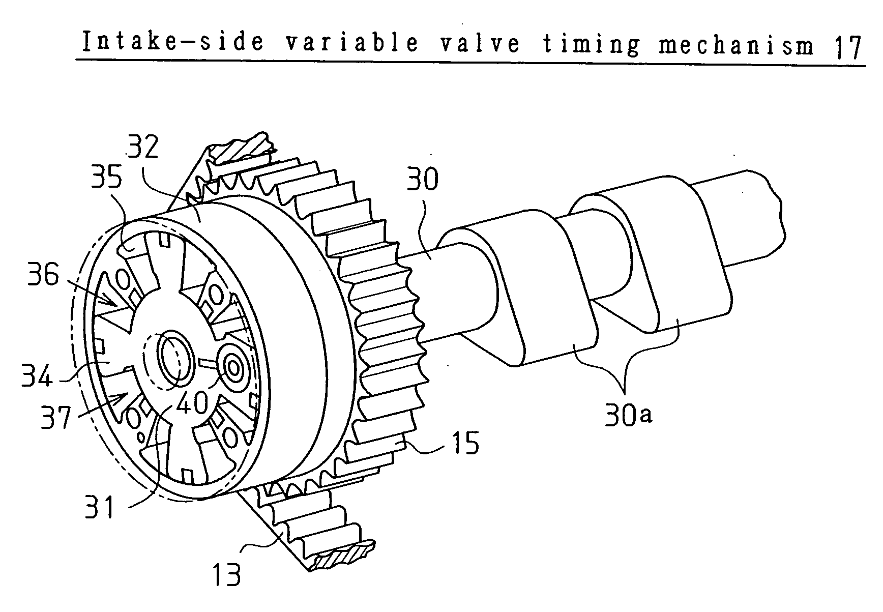
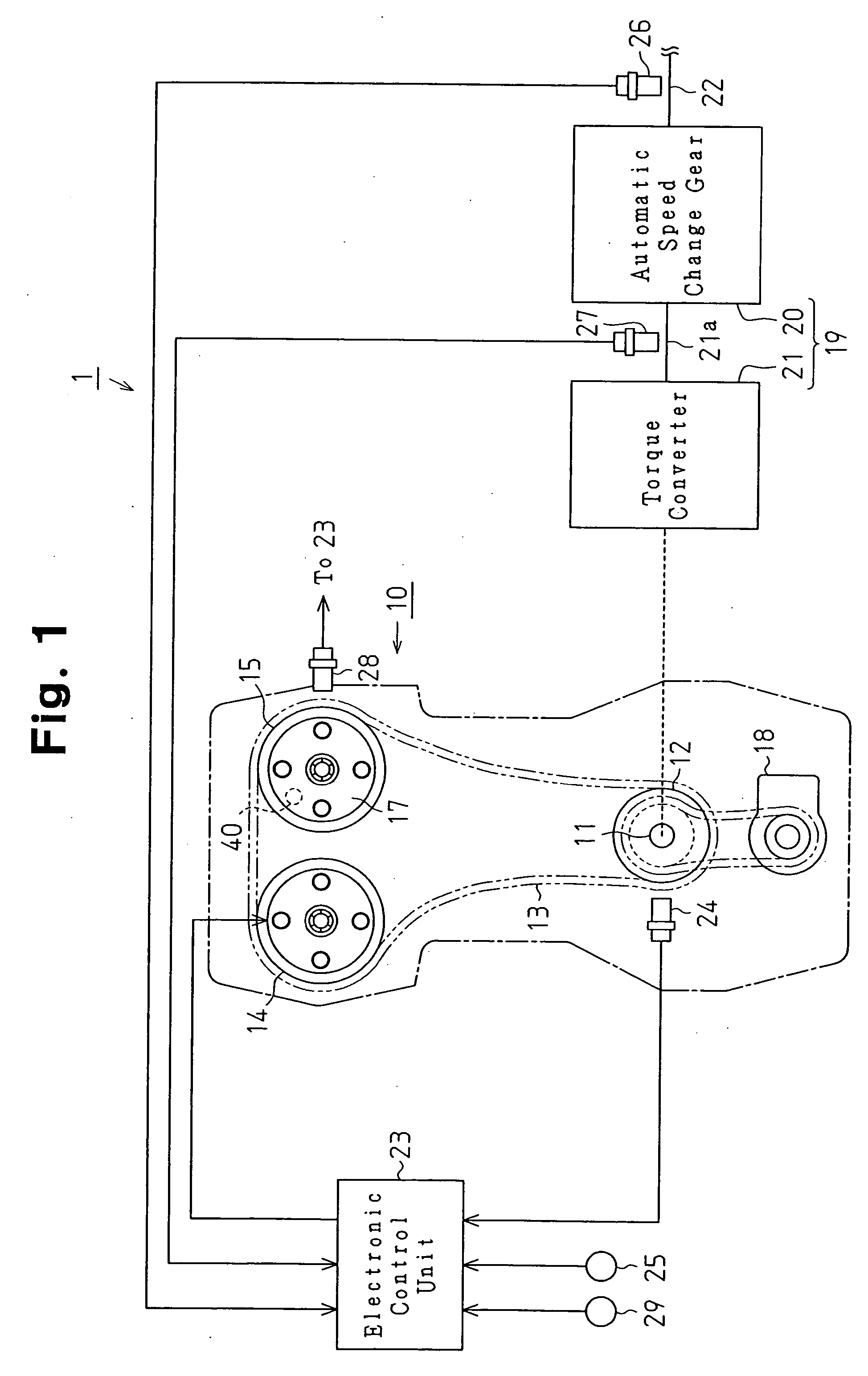
[0037] A first embodiment embodying the present invention will now be described. FIG. 1 shows a schematic configuration of a vehicle to which this embodiment is applied. As shown in FIG. 1, at one end of a crankshaft 11, which is an output shaft of an internal combustion engine 10 mounted on a vehicle 1, a crank pulley 12 is fixed so as to be rotatable integrally. The crank pulley 12 is connected drivingly to an exhaust-side cam pulley 14 provided at one end of an exhaust-side camshaft and an intake-side cam pulley 15 provided at one end of an intake-side camshaft via a timing belt 13. The exhaust-side cam pulley 14 is connected to the exhaust-side camshaft, and the intake-side cam pulley 15 is connected to the intake-side camshaft via a variable valve timing mechanism 17, which functions as a variable valve actuation mechanism.

[0038] The crankshaft 11 is also connected drivingly to a pump 18 via, for example, a timing belt. The crankshaft 11 is connected drivingly to an axle 22 via...

second embodiment

[0130] In the above-described second embodiment, the degree of change restriction of the valve timing VI of intake valve may be set so as to be higher as the difference ΔVE increases. According to this configuration, the change of valve timing VI of the intake valve can be restricted so that a difference in the convergence speed between valves is a desired speed difference, and the temporary stagnation of increase in engine rotational speed NE can be restrained appropriately. Such a configuration can be realized by a configuration, for example, such that a smaller value is calculated as the upper limit value γ2 as the difference ΔVE increases.

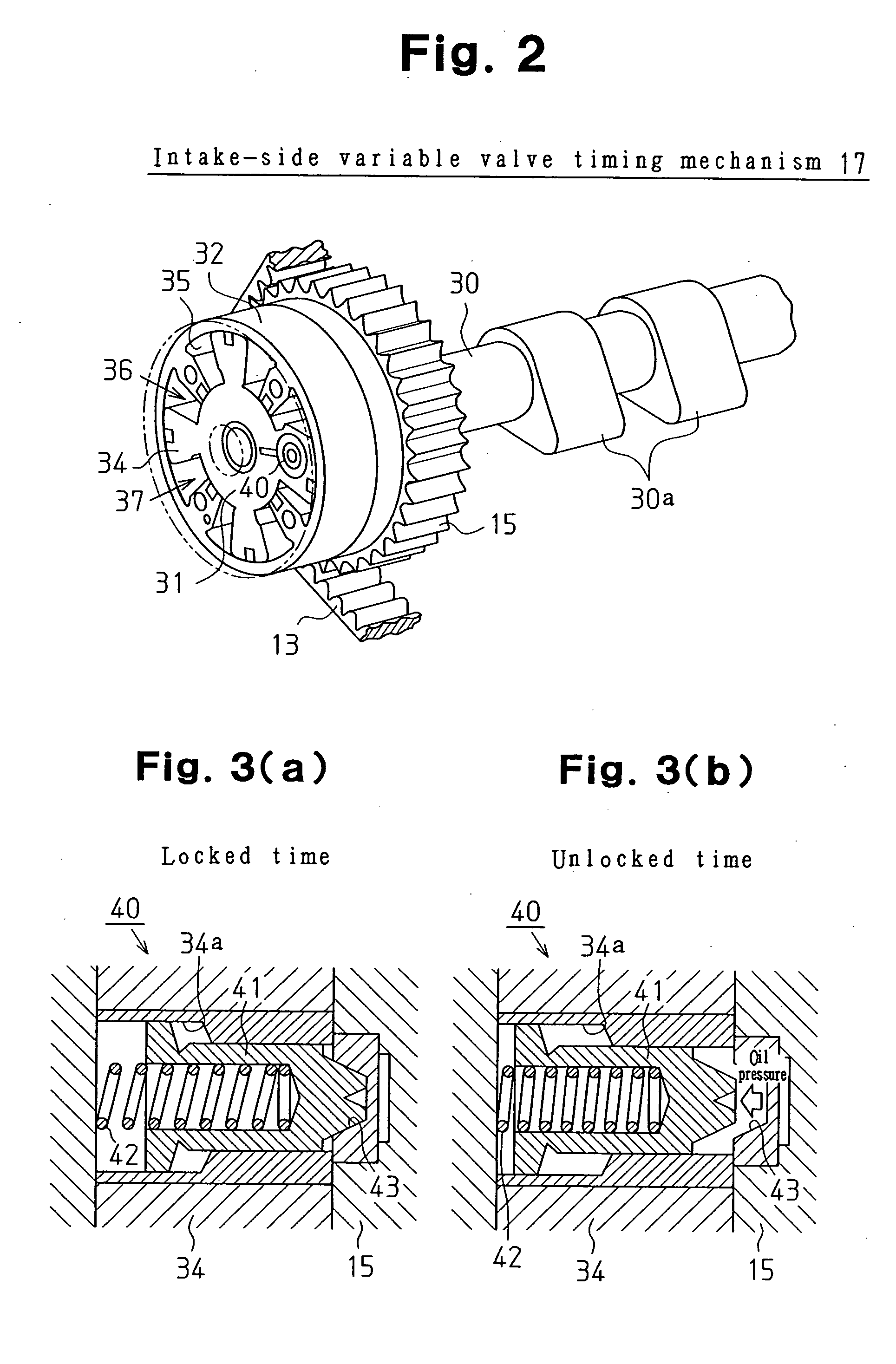
[0131] In the above-described second embodiment, the processing in Step S106 for valve timing change processing may be omitted. This configuration can also be applied to an internal combustion engine that does not have the lock mechanism 40 and the lock mechanism 51.

[0132] The present invention can be applied to not only a hydraulically operat...


PUM


Abstract

A controller restricts an operation amount of the variable valve actuation mechanism of a fluid pressure operated type such that increase in the valve overlap amount of an engine is restrained when the engine is in a transient operation state in which the output of the engine increases. When the controller determines that the variable valve actuation mechanism is in the locked state, the controller relaxes the restriction imposed on the operation amount of the variable valve actuation mechanism. Hence, a decrease in follow-up performance of valve properties to desired properties is restrained while restraining temporary stagnation of increase in engine rotational speed caused by vehicle acceleration.

Description

BACKGROUND OF THE INVENTION [0001] The present invention relates to a control apparatus for an internal combustion engine, which is provided with a variable valve actuation mechanism for changing the valve properties of engine valves. The present invention also pertains to a method for controlling an internal combustion engine. [0002] Usually, in starting a vehicle, after the rotational speed of an engine has increased to some extent, a friction clutch is engaged to start power transmission from an engine output shaft to an axle. In starting a vehicle provided with a liquid clutch such as a torque converter, likewise, power transmission to an axle is started after the rotational speed of an engine has increased to some extent. Therefore, depending on the mode of power transmission, for example, as shown in FIG. 18, when power transmission is started, that is, when a rotational speed NT of a clutch output shaft starts to increase (time t31), the increase rate of an engine rotational ...

Claims


Application Information

Patent Timeline
IPC IPC(8): F01L1/34F01L1/344F02D13/02F02D41/10
CPCF01L1/3442F01L2001/0537F01L2001/34453F01L2800/00Y02T10/18F02D13/0261F02D41/10F02D2041/001F02D13/0215Y02T10/12
Inventor HIROWATARI, SEIJIIDOGAWA, MASANAOTAKAGI, ISAOKISHI, HIROHISA
Owner TOYOTA JIDOSHA KK
Why Eureka
Try Eureka