
Process designed to prevent deposition of contaminating particles on the surface of a micro-component, micro-component storage device and thin layer deposition device

a technology of microcomponents and storage devices, applied in the direction of electrodes, chemical vapor deposition coatings, ion implantation coatings, etc., can solve the problems of optical layer defects, deformation of optical layers, and degradation of layers in operation or even preventing functioning, so as to reduce the risk of contamination, and the effect of simple and reproducibl

Inactive Publication Date: 2005-03-10
COMMISSARIAT A LENERGIE ATOMIQUE ET AUX ENERGIES ALTERNATIVES
View PDF4 Cites 11 Cited by
  • Summary
  • Abstract
  • Description
  • Claims
  • Application Information

AI Technical Summary

Benefits of technology

[0009] One object of the invention is to reduce the risk of contaminating the free surface of a micro-component arranged in a vacuum chamber, by deposition of parasite particles, in an efficient, simple and reproducible manner.
[0014] Another object of the invention is to achieve a storage device designed to store at least one micro-component, protecting the surface thereof efficiently and simply from a possible deposition of contaminating particles.
[0016] Another object of the invention is to achieve a thin layer deposition device efficiently limiting the risk of contamination of the thin layer by deposition of contaminating particles.

Problems solved by technology

The defects formed in a thin layer can in fact degrade the layer in operation or even prevent functioning thereof.
Thus, in layers having a mechanical function such as anti-wear, anti-corrosion or lubricating layers, defects constitute weakness points which may give rise to wear of the layer.
Likewise, the defects formed in optical layers can generate malfunctions.
The defects present on the surface of the mask or in the first layers of the reflector are liable to disturb the image of the projected pattern.
This disturbance may create breaks in the tracks or defects in the circuit patterns at the level of the printed circuit, on the silicon.
However deposition techniques of the thin layers forming the reflector are known to generate defects.
Indeed, even the Ion Beam Sputtering (IBS) deposition technique generally used to achieve the reflector of an EUV mask is not satisfactory.
As the sputtering source itself generates contaminating particles having a size smaller than 150 nm, it is in fact extremely difficult to limit the defect densities to the imposed level and in reproducible manner.
These modifications do not however enable the required defect rates for EUV lithography masks to be obtained in reproducible manner.

Method used


Image

  • Process designed to prevent deposition of contaminating particles on the surface of a micro-component, micro-component storage device and thin layer deposition device
  • Process designed to prevent deposition of contaminating particles on the surface of a micro-component, micro-component storage device and thin layer deposition device
  • Process designed to prevent deposition of contaminating particles on the surface of a micro-component, micro-component storage device and thin layer deposition device

Examples


Embodiment Construction

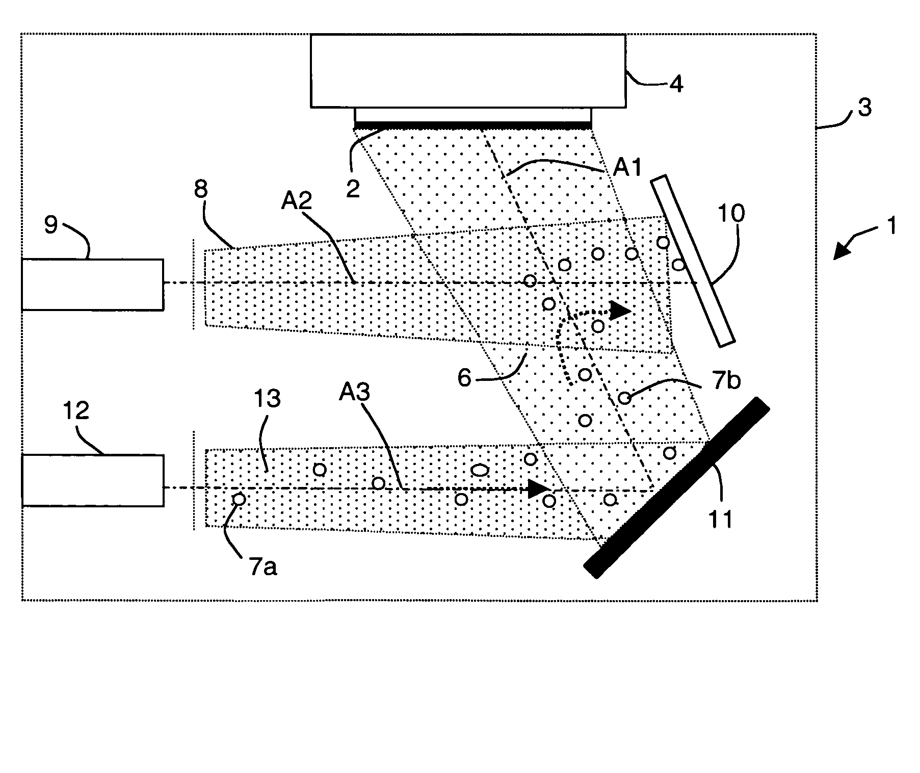
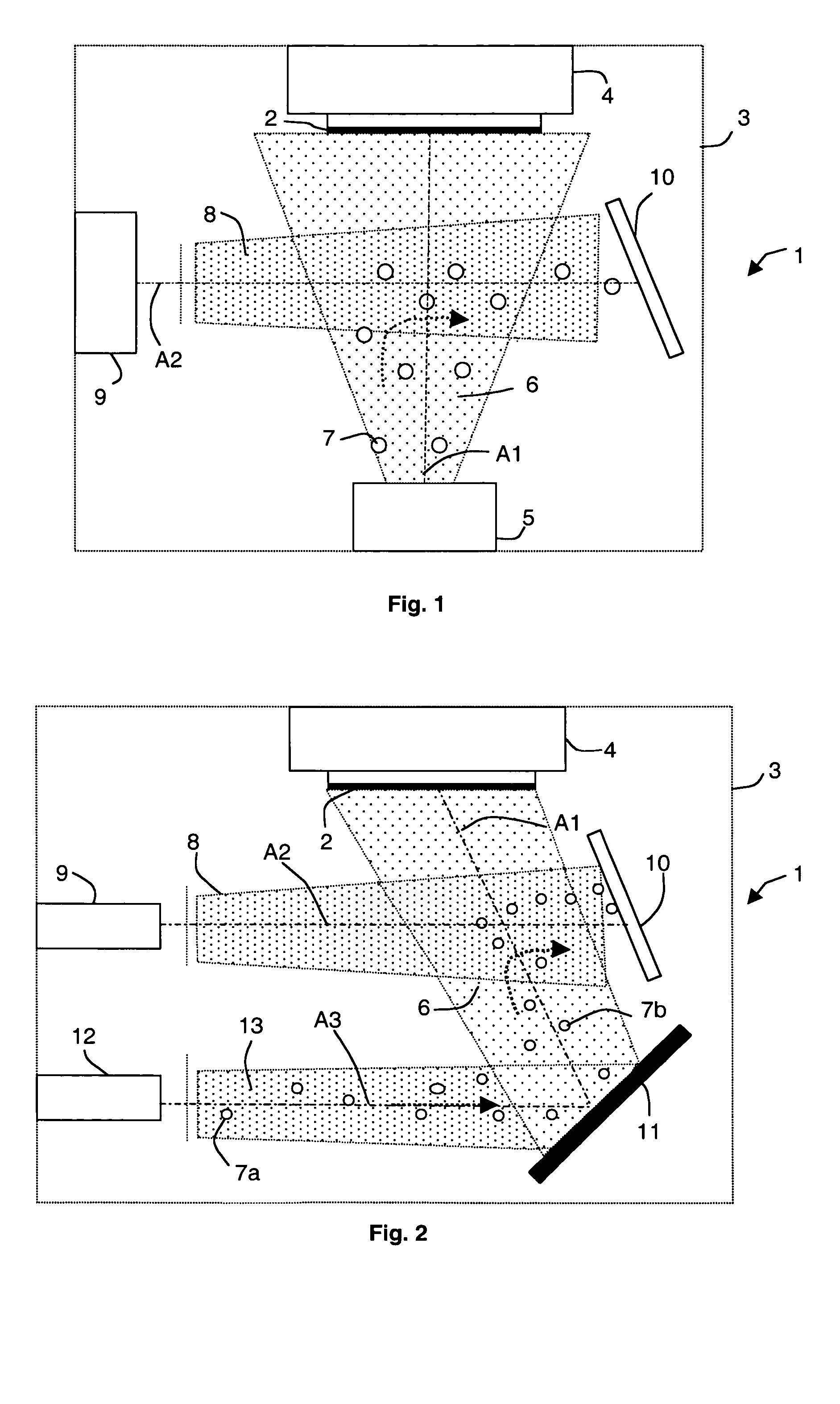
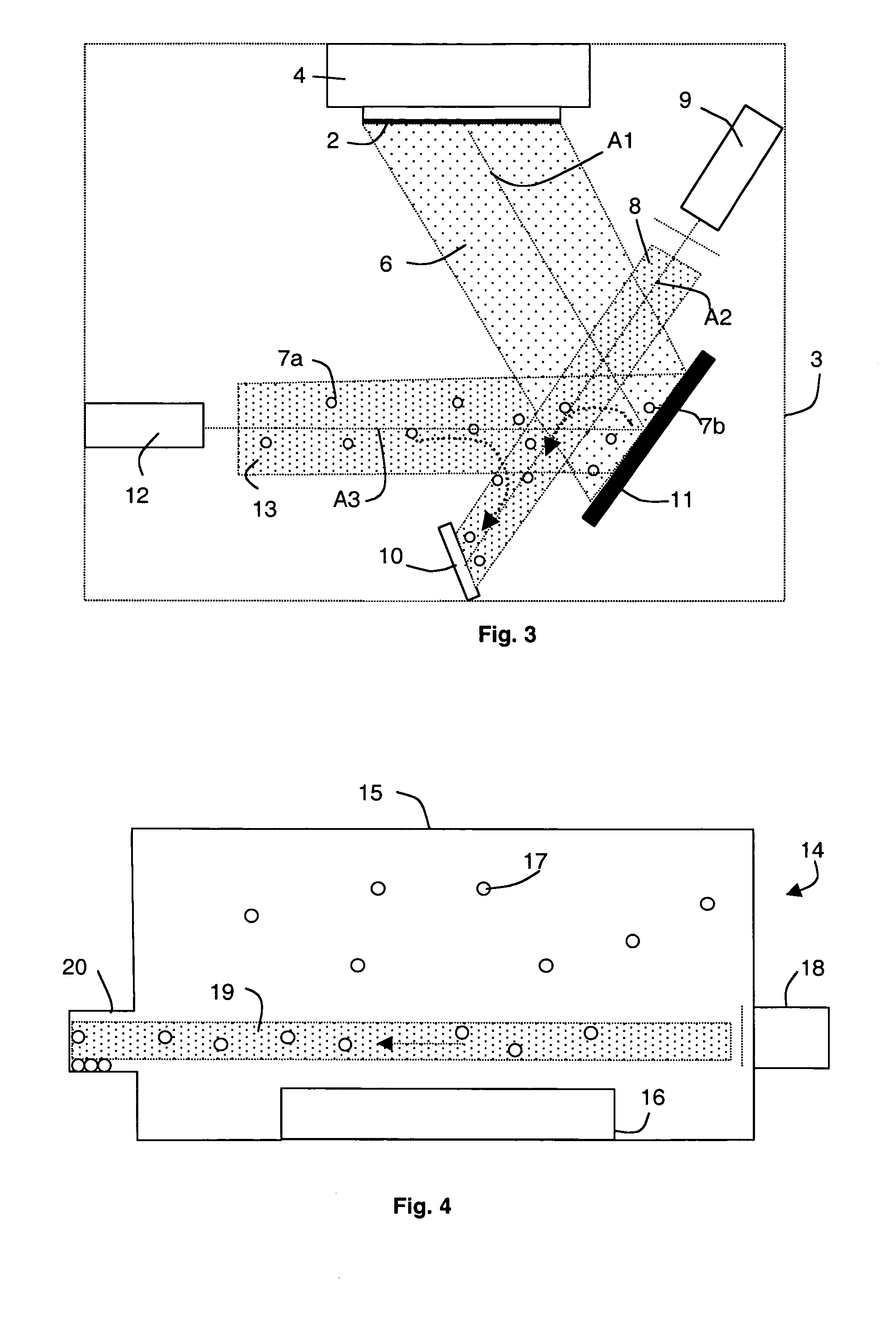
[0023] According to the invention, a process designed to prevent deposition of polarized contaminating particles originating from a contamination source on the free surface of a micro-component consists in sputtering a beam of particles at least a part whereof has an opposite polarity from that of the contaminating particles. The micro-component is arranged in the vacuum chamber. The beam of particles is sputtered between the contamination source and the micro-component and is designed to drag the contaminating particles away from the micro-component to a collecting element. The beam of particles is preferably a plasma.

[0024] Thus, according to FIG. 1, a device 1 implementing such a process is designed to deposit at least one thin layer on a substrate 2 so as to form a micro-component. The device 1 comprises a vacuum chamber 3 wherein there are respectively deposited, on two opposite walls, a substrate holder 4 comprising the substrate 2 and a source 5 designed to sputter a flow 6 ...


PUM

PropertyMeasurementUnit
Electric potential / voltageaaaaaaaaaa
Flow rateaaaaaaaaaa

Abstract

A process designed to prevent deposition of polarized contaminating particles on the surface of a micro-component consists, according to the invention, in sputtering a beam of particles between the contamination source and the micro-component. At least a part of the particles of the beam has an opposite polarity from that of the contaminating particles. The beam of particles is preferably a plasma and is designed to drag the contaminating particles away from the free surface of the micro-component to a collecting element. The invention also relates to a micro-component storage device and a thin layer deposition device respectively implementing such a process.

Description

BACKGROUND OF THE INVENTION [0001] The invention relates to a process designed to prevent deposition of polarized first particles originating from at least one contamination source on the free surface of a micro-component arranged in a vacuum chamber. [0002] The invention also relates to a storage device implementing such a process and comprising a vacuum chamber wherein there is arranged at least one micro-component. [0003] The invention also relates to a thin layer deposition device implementing such a process and comprising a vacuum chamber wherein there is arranged a micro-component comprising at least one substrate and means for sputtering a flow of matter designed to form at least one thin layer on the surface of the micro-component. STATE OF THE ART [0004] Thin layers used in particular in optical or mechanical applications must comprise a limited number of defects and the tolerated defects must have a critical size. The defects formed in a thin layer can in fact degrade the ...

Claims


Application Information

Patent Timeline
IPC IPC(8): C23C14/34C23C4/12C23C14/22C23C14/56C23C16/44C23C26/00
CPCC23C4/127C23C14/22C23C26/00C23C16/4401C23C14/564C23C4/134
Inventor QUESNEL, ETIENNEMUFFATO, VIVIANE
Owner COMMISSARIAT A LENERGIE ATOMIQUE ET AUX ENERGIES ALTERNATIVES
Learn More