Virtual image display apparatus

a virtual image and display technology, applied in the field of virtual image display apparatus, can solve the problems of reducing visibility, giving an uncomfortable feeling to the observer, and affecting the quality of images, and achieve the effect of high quality

Inactive Publication Date: 2005-03-10
DENSO CORP
View PDF6 Cites 45 Cited by
  • Summary
  • Abstract
  • Description
  • Claims
  • Application Information

AI Technical Summary

Benefits of technology

[0021] The present invention is made in view of the above problems, and it is an object of the present invention to provide a virtual image display apparatus, which is smaller with a simpler structure and which realizes an image display of a high quality.
[0025] According to another feature of the present invention, an optical magnifying device can be added to the above apparatus, so that the apparatus can be further made smaller.
[0027] According to a further feature of the present invention, a single set of optical projection system can be provided, wherein images are displayed on a display device in a time-sharing manner, and separated to the respective images for the left and right eyes, so that the same effect to the apparatus having the pair of optical projection systems can be obtained.
[0028] According to a further feature of the present invention, an optical combining device is provided for combining the respective images from the pair of optical projection systems, and the combined images are reflected by the translucent reflecting means, so that the virtual image of the high quality can be obtained without using an optical diffusion device.

Problems solved by technology

In this situation, when a distance of a display image is largely changed, it may give an uncomfortable feeling to the observing person.
Furthermore, in the conventional apparatus having a pair of optical projection systems and a field lens, wherein the light rays from the respective optical projection systems are collected at the left and right eyes by the use of the field lens, an optical axis of the pair of projection systems is displaced from an optical axis of the field lens, causing an aberration.
As a result, the light rays from the whole area of the lens may not be collected at one observing point, so that the whole image can not be recognized by the observing person, causing a hiatus of the image.
Furthermore, when the displayed image is made larger, the field lens must be made larger, and thereby the aberration becomes inevitably much larger, decreasing the visibility.
Accordingly, even when a position of the observing points is detected to control the light rays, it is difficult to obtain a high visibility.
As above, there are many problems in the conventional apparatuses, namely an optical system becomes larger in case that the some of the optical devices of the system is mechanically moved, a visibility is decreased (a hiatus of image) because of the aberration of lens, and an optical system becomes larger in case that an exit pupil is made larger.

Method used


Image

  • Virtual image display apparatus
  • Virtual image display apparatus
  • Virtual image display apparatus

Examples


first embodiment

[0043] (First Embodiment) The present invention will be explained below with reference to the embodiments.

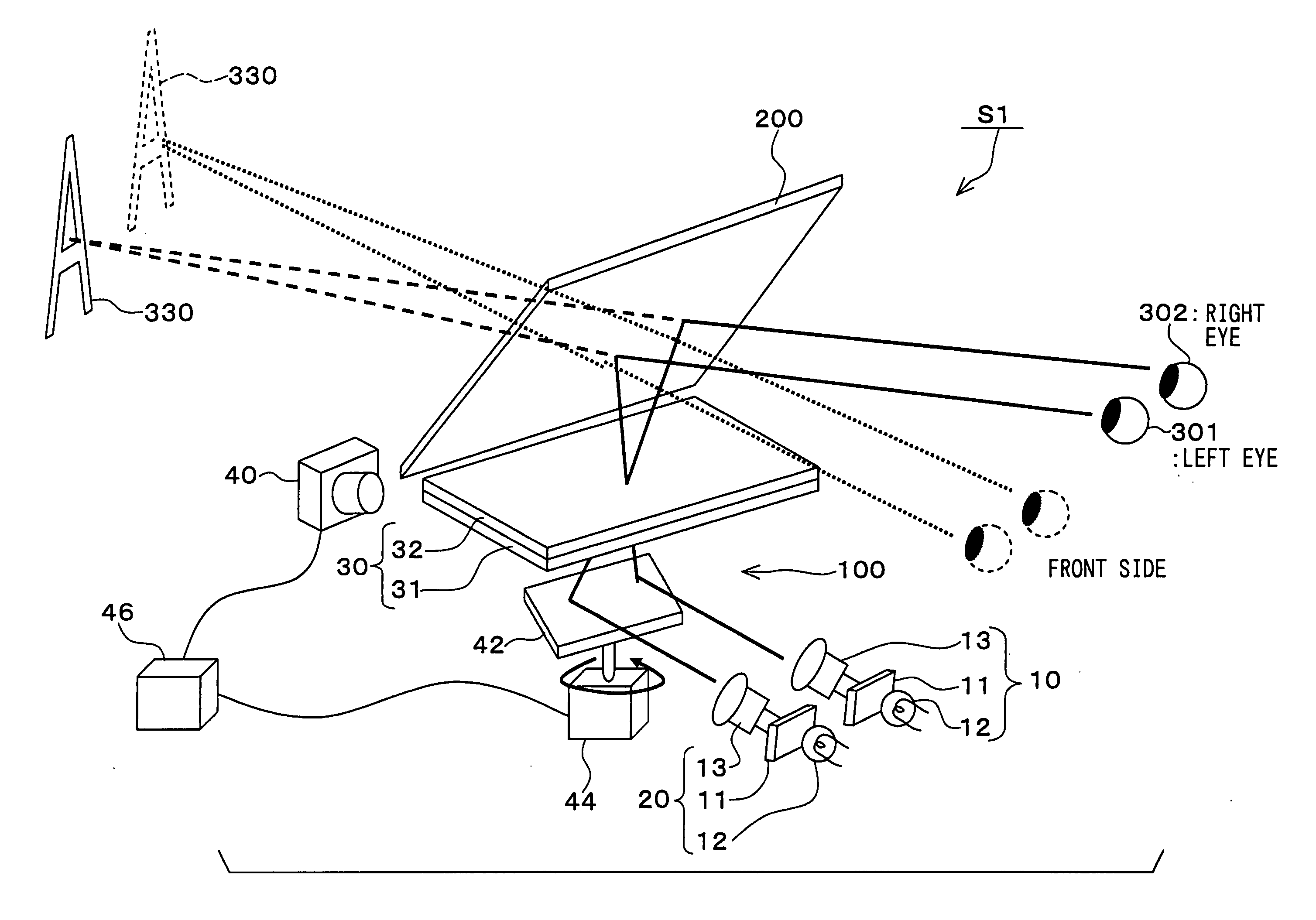
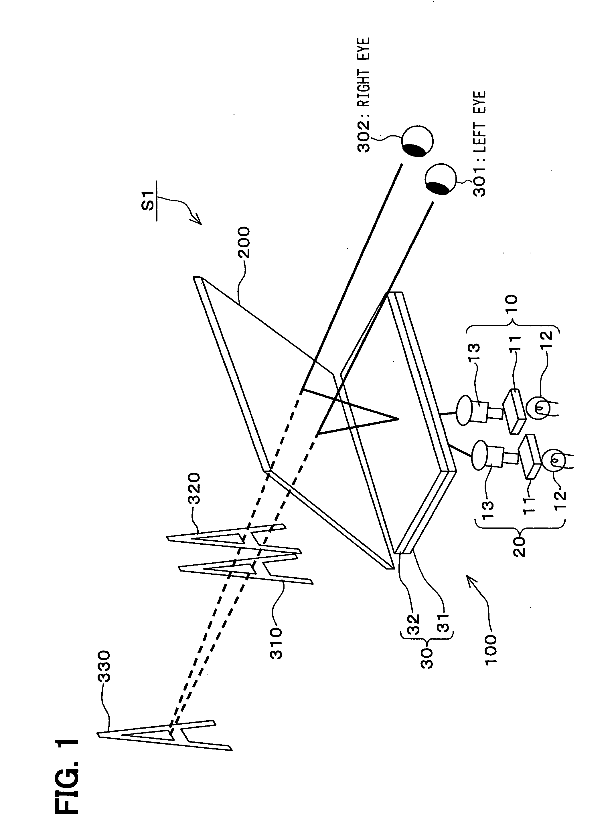
[0044] In FIG. 1, showing a schematic structure of a virtual image display apparatus S1 according to a first embodiment of the present invention, an image information projected from an optical unit 100 is reflected by a translucent reflecting plate 200 so that the image information becomes visible to an observing person as a virtual image from its observing points (eyes) 301, 302, wherein the virtual images are overlapped to each other in the distance.

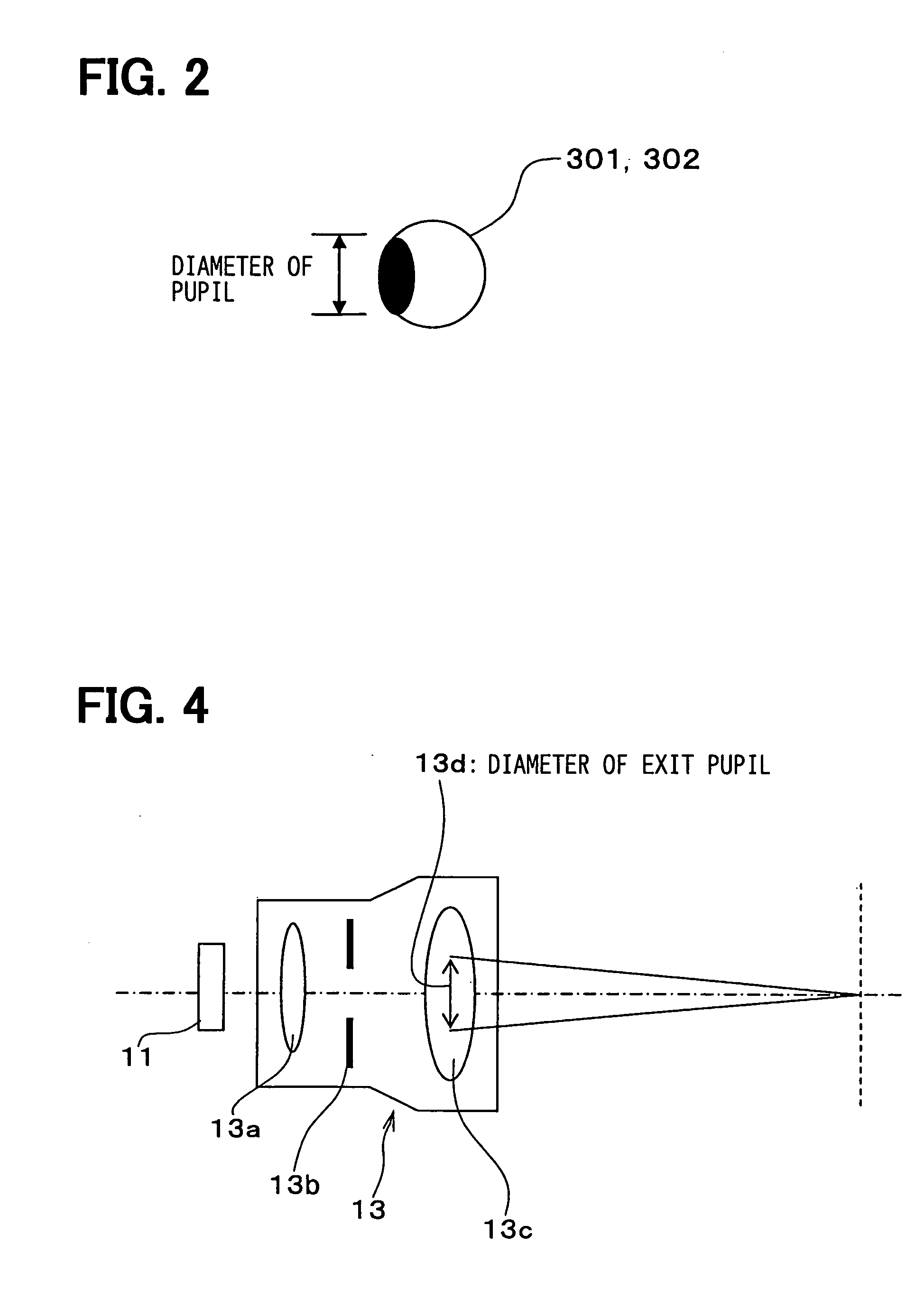
[0045]FIG. 2 shows an eye (301, 302) of the observing person, wherein a black portion corresponds to a pupil of the eye, and a length of the black portion is a diameter of the pupil.

[0046] The optical unit 100 comprises a pair of optical projection systems, namely an optical projection system 10 for a left eye 301 and an optical projection system 20 for a right eye 302.

[0047] Each of the optical projection systems 10, 20 has a d...

second embodiment

[0101] (Second Embodiment)

[0102]FIG. 8 is a schematic view of a virtual image display apparatus S2 according to a second embodiment of the present invention, wherein a prism sheet 33 is added to the image location optical system 30 of the apparatus S1 shown in FIG. 1.

[0103] In FIG. 8, the prism sheet 33 is provided in the group of lens (the image location optical system) 30, wherein the prism sheet 33 is in contact with the Fresnel lens 31. The light rays are refracted by the prism sheet 33.

[0104] The prism sheet 33 here is an optical device being composed of stripe shaped microscopic prisms and having a function of refracting the light rays. It becomes possible with this prism sheet 33 to incident the light rays from the optical projection systems 10, 20 in a direction, which is inclined with respect to a surface of the group of lenses 30.

[0105] In this prism sheet 33, an angle (an exit angle) of outgoing light ray is made smaller than an incident angle of the light rays from th...

third embodiment

[0109] (Third Embodiment)

[0110]FIG. 9 is a schematic view of a virtual image display apparatus S3 according to a third embodiment of the present invention, wherein a magnifying Fresnel lens 34 is added to the apparatus S1 shown in FIG. 1.

[0111] The magnifying Fresnel lens 34 is arranged at such a position, which is separate from the group of lenses 30 (the collecting Fresnel lens 31 and the micro lens array 32) and closer to the observing person. The lens 34 has a function of magnifying the image on the group of lenses 30.

[0112] In the apparatus in FIG. 1, the images of the optical projection systems 10, 20 are formed on the group of lenses 30 and the virtual images thereof are displayed by the half mirror 200. Accordingly, the optical path length from the observing points 301, 302 to the group of lenses 30 corresponds to an image forming length of the virtual image from the observing points 301, 302.

[0113] When a visible distance of an image fusing point (the visible position), ...


PUM


Abstract

A virtual image display apparatus comprises a pair of optical projection systems, each having a display device, a light source and a projection lens. The images formed on the display device are projected to an image location optical system, which comprises a light collecting lens and an optical diffusion device. The light rays from the optical projection systems are reflected at a translucent reflecting means, so that the light rays are respectively collected at right and left eyes of an observing person. As a result, the images can be recognized by the person as a virtual image in the distance. Since the optical diffusion device diffuses the light rays, in such a way that the light rays to one of observing eyes may not reach the other observing eye, so that the image information of the respective light rays can be recognized by the observing person, without causing a cross-talk.

Description

CROSS REFERENCE TO RELATED APPLICATION [0001] This application is based on Japanese Patent Application No. 2003-298322 filed on Aug. 22, 2003, the disclosure of which is incorporated herein by reference. FIELD OF THE INVENTION [0002] This invention relates to a virtual image display apparatus, which makes visible a virtual image on a translucent reflecting means from observing points by reflecting image information projected from an optical unit on the translucent reflecting means and overlapping the virtual image to a foreground. [0003] The virtual image display apparatus of this kind is generally used in a display system, in which an additional image is displayed as a virtual image on a monitor in front of an observing person and the additional image is overlapped to an image or already displayed on the monitor or a forward landscape, and in particular used as an information display apparatus for an entertainment apparatus such as a computer game or an automobile. BACKGROUND OF TH...

Claims


Application Information

Patent Timeline
Patent Type & Authority Applications(United States)
IPC IPC(8): G02B27/01B60K35/00G02B30/29H04N13/00
CPCG02B27/225H04N13/0404H04N13/0402H04N13/302H04N13/305G02B30/29
Inventor FUJIKAWA, TAKAYUKIANDO, HIROSHI
Owner DENSO CORP
Why Eureka
Try Eureka