Foamed dustproof material and dustproof structure using foamed dustproof material

Inactive Publication Date: 2005-03-10
NITTO DENKO CORP
View PDF5 Cites 20 Cited by
  • Summary
  • Abstract
  • Description
  • Claims
  • Application Information

AI Technical Summary

Benefits of technology

[0008] In recent years, however, a product having an optical member (such as an image displaying device, a camera and a lens) installed therein is becoming to have a thin profile, and associated thereto, the clearance of the part where the dustproof material is applied tends to be decreased. More recently,

Problems solved by technology

More recently, such a situation occurs that a conventional dustproof material having been used cannot be applied due to the large repulsive force thereof.
The gasket disclosed in JP-A-2001-100216 (i.e., a gasket formed with a

Method used


Image

  • Foamed dustproof material and dustproof structure using foamed dustproof material
  • Foamed dustproof material and dustproof structure using foamed dustproof material

Examples


example 1

[0119] 45 parts by weight of polypropylene, 45 parts by weight of a polyolefin elastomer, 10 parts by weight of polyethylene, 10 parts by weight of magnesium hydroxide and 10 parts by weight of carbon were kneaded in a biaxial kneader produced by Japan Steel Works, Ltd. (JSW) at a temperature of 200° C., and extruded into a strand form, which was then cooled with water and molded into pellets. The pellets were placed in a uniaxial extruder produced by Japan Steel Works, Ltd., to which a carbon dioxide gas was injected under an atmosphere of 220° C. at a pressure of 13 MPa, which was lowered to 12 MPa after completing the injection.

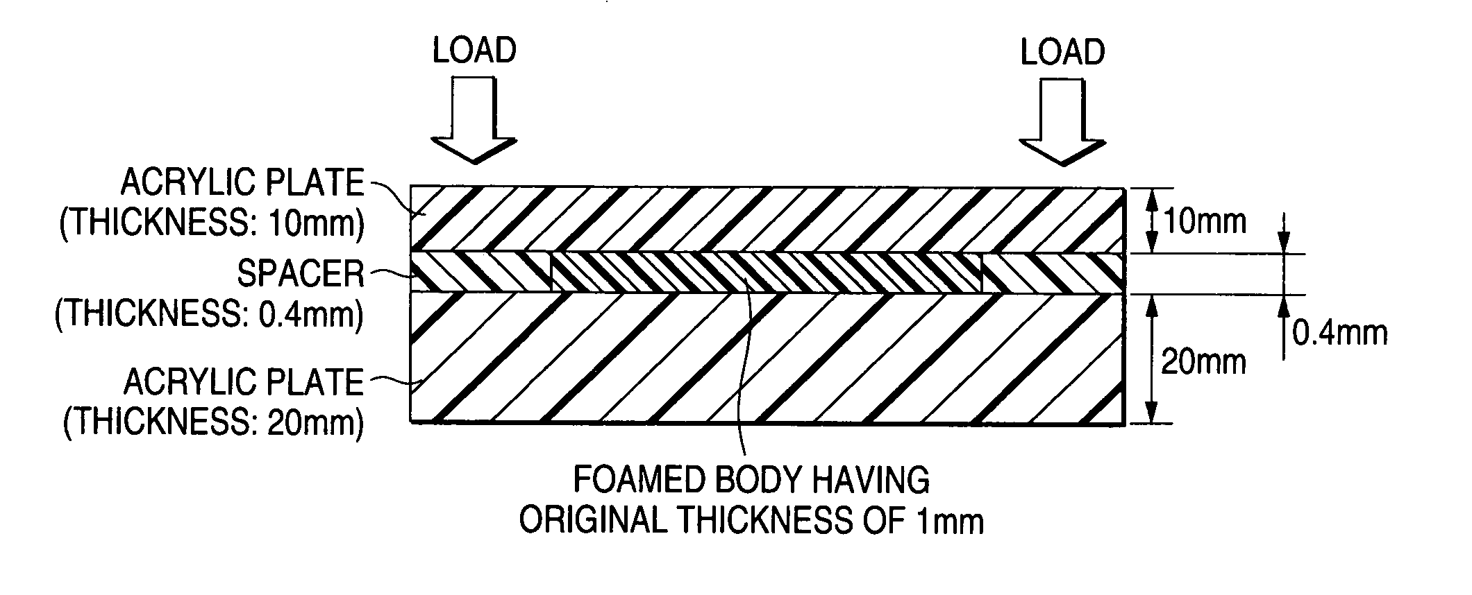
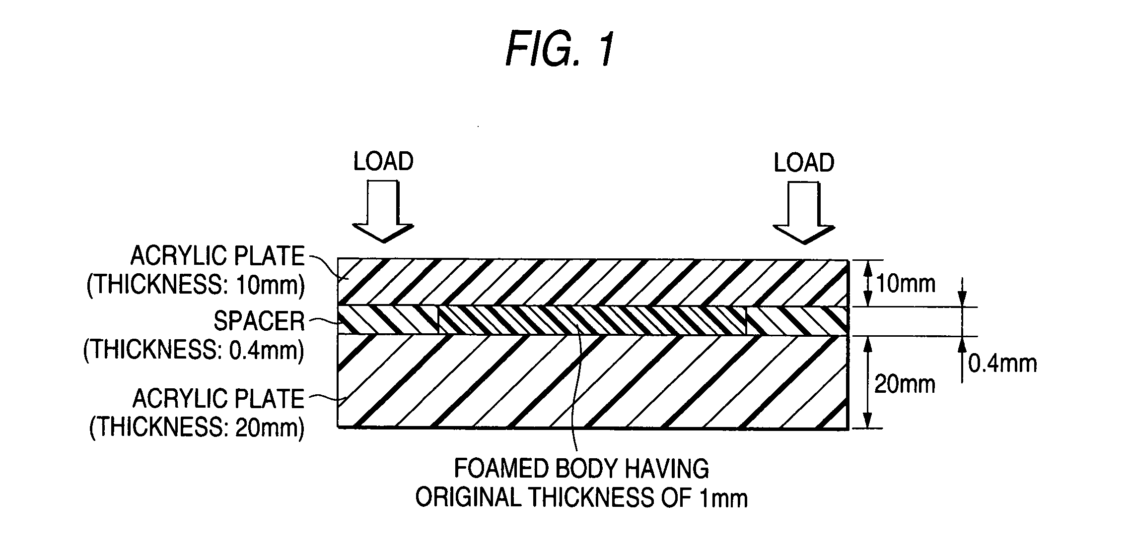
[0120] The carbon dioxide gas was injected in a ratio of 5% by mass based on the total amount of the polymer. After sufficiently saturating the carbon dioxide gas, the mixture was cooled to a temperature suitable for foaming, and then extruded from a die to obtain a foamed body. The foamed body thus obtained had an average cell diameter of 70 μm, a load a...

example 2

[0121] 30 parts by weight of polypropylene, 60 parts by weight of a polyolefin elastomer, 10 parts by weight of polyethylene, 10 parts by weight of magnesium hydroxide and 10 parts by weight of carbon were kneaded in a biaxial kneader produced by Japan Steel Works, Ltd. at a temperature of 200° C., and extruded into a strand form, which was then cooled with water and molded into pellets. The pellets were placed in a uniaxial extruder produced by Japan Steel Works, Ltd., to which a carbon dioxide gas was injected under an atmosphere of 220° C. at a pressure of 13 MPa, which was lowered to 12 MPa after completing the injection.

[0122] The carbon dioxide gas was injected in a ratio of 5% by mass based on the total amount of the polymer. After sufficiently saturating the carbon dioxide gas, the mixture was cooled to a temperature suitable for foaming, and then extruded from a die to obtain a foamed body. The foamed body thus obtained had an average cell diameter of 80 μm, a repulsive fo...

example 3

[0123] 60 parts by weight of polypropylene, 30 parts by weight of a polyolefin elastomer, 10 parts by weight of polyethylene, 10 parts by weight of magnesium hydroxide, 10 parts by weight of carbon and 1 part by weight of stearic acid monoglyceride were kneaded in a biaxial kneader produced by Japan Steel Works, Ltd. at a temperature of 200° C., and extruded into a strand form, which was then cooled with water and molded into pellets. The pellets were placed in a uniaxial extruder produced by Japan Steel Works, Ltd., to which a carbon dioxide gas was injected under an atmosphere of 220° C. at a pressure of 13 MPa, which was lowered to 12 MPa after completing the injection.

[0124] The carbon dioxide gas was injected in a ratio of 5% by mass based on the total amount of the polymer. After sufficiently saturating the carbon dioxide gas, the mixture was cooled to a temperature suitable for foaming, and then extruded from a die to obtain a foamed body. The foamed body thus obtained had a...


PUM

PropertyMeasurementUnit
Lengthaaaaaaaaaa
Fractionaaaaaaaaaa
Pressureaaaaaaaaaa

Abstract

A foamed dustproof material which comprises a foamed body, wherein the foamed body has an average cell diameter of from 10 to 90 μm, a load against repulsion upon compressing to 50% of from 0.1 to 3.0 N/cm2, and an apparent density of from 0.01 to 0.10 g/cm3.

Description

FIELD OF THE INVENTION [0001] The present invention relates to a foamed dustproof material and a dustproof structure using the foamed dustproof material, and more particularly, relates to such a foamed dustproof material that has excellent dustproof property and can successfully follow a minute clearance, and a dustproof structure using the foamed dustproof material. BACKGROUND ART [0002] A dustproof material has been used upon mounting an image displaying member fixed to an image displaying device, such as a liquid crystal display, an electroluminescence display and a plasma display, and an optical member, such as a camera and a lens, fixed to a potable phone or a portable information device, on a prescribed site, such as a fixing part. A dustproof material has also been used for preventing a toner from leaking from a toner cartridge used in an image forming apparatus, such as a duplicator and a printer. [0003] As the dustproof material, a polyethylene foamed body having closed cel...

Claims


Application Information

Patent Timeline
IPC IPC(8): B32B3/00B32B3/26B32B9/00C08J9/00C08J9/08C08J9/12C09J7/02C09K3/22G02F1/1339H01H1/10
CPCC08J9/0061C08J9/122C08J2201/03C08J2423/00C08J2203/08C08J2323/14C08J2201/032Y10T428/249953Y10T428/249976Y10T428/249977Y10T428/249978Y10T428/249979Y10T428/249987C09J7/26C09J7/38
Inventor SAITOU, MAKOTOTAKAHASHI, NOBUYUKITACHIBANA, KATSUHIKO
Owner NITTO DENKO CORP
Why Eureka
Try Eureka