Method and device for operating at least one turbocharger on an internal combustion engine

a technology of internal combustion engine and supercharger, which is applied in the direction of combustion engines, electric control, machines/engines, etc., can solve the problems of co-coupling of exhaust gas turbochargers and unstable performance, and achieve advantageously minimize the load on the battery

Inactive Publication Date: 2005-03-17
ROBERT BOSCH GMBH
View PDF16 Cites 23 Cited by
  • Summary
  • Abstract
  • Description
  • Claims
  • Application Information

AI Technical Summary

Benefits of technology

The start time and the duration of the electrical auxiliary compressor's operation are advantageously derived on the basis of the exhaust gas volume flow by running the auxiliary compressor only until the exhaust gas volume flow reaches the volume flow demand of the turbine. In this

Problems solved by technology

Without pneumatic counter-coupling the exhaust gas

Method used


Image

  • Method and device for operating at least one turbocharger on an internal combustion engine
  • Method and device for operating at least one turbocharger on an internal combustion engine
  • Method and device for operating at least one turbocharger on an internal combustion engine

Examples


Embodiment Construction

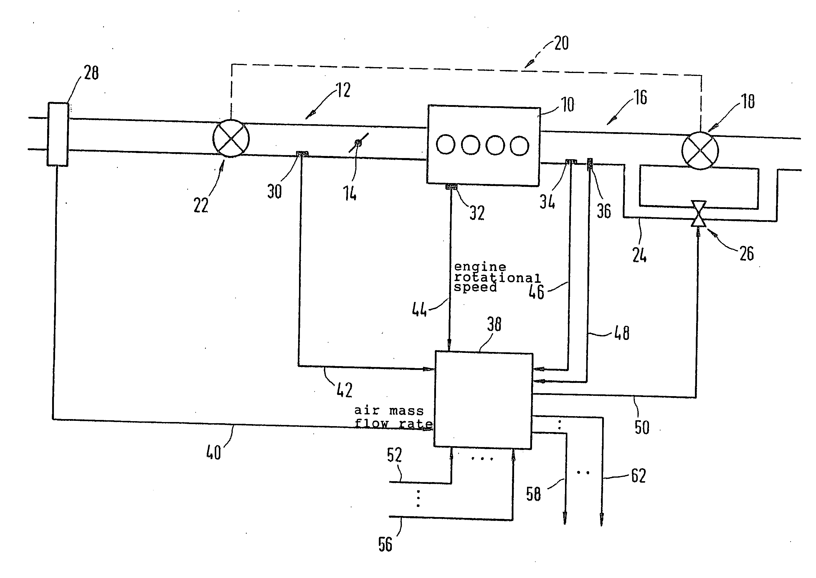
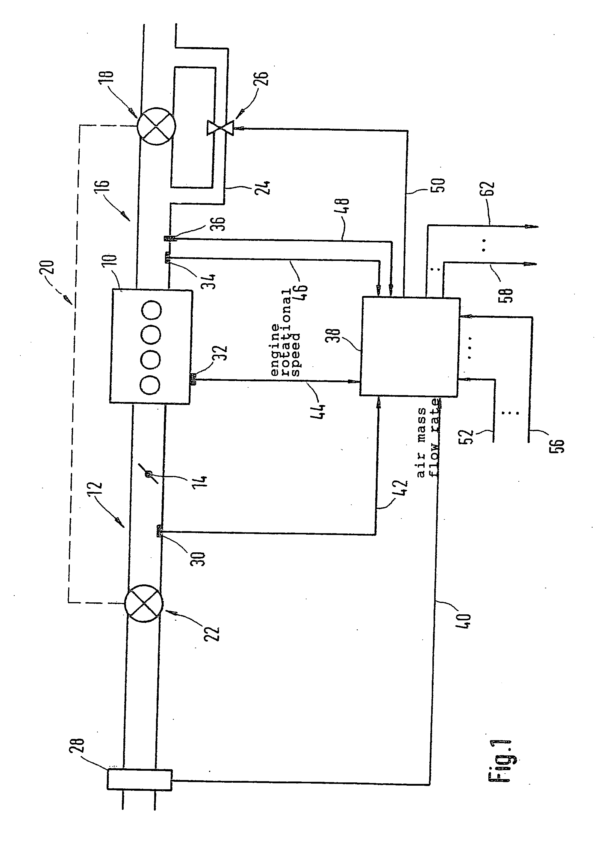
In the general diagram shown in FIG. 1, an internal combustion engine 10 is illustrated which includes an intake system 12 having a throttle valve 14, and an exhaust gas system 16. Turbine 18 of an exhaust gas turbocharger is situated in exhaust gas system 16, and the turbine is connected to compressor 22, which is situated at the intake manifold, via a mechanical connection 20. An electrically actuatable valve 26 is provided in a bypass duct 24 around turbine 18 of the exhaust gas turbocharger. Various sensors are installed for detecting different performance quantities in the region of the internal combustion engine. A selection of these sensors is illustrated in FIG. 1 with a view to the procedure described below: an air mass flow meter 28, an intake manifold pressure sensor 30, an engine rotational speed sensor 32, an exhaust gas pressure sensor 34, and an exhaust gas temperature sensor 36. An electronic controller 38 is also illustrated which receives lines from the above-ment...


PUM


Abstract

A method and a device for operating at least one supercharger of an internal combustion engine is described, the actuating signal for at least one actuating element of the supercharger (waste gate actuator, electrical auxiliary compressor) being generated as a function of the exhaust gas volume flow in the exhaust tract of the internal combustion engine.

Description

FIELD OF THE INVENTION The present invention relates to a method and a device for operating at least one supercharger of an internal combustion engine. BACKGROUND INFORMATION Exhaust gas turbochargers are used in some applications for increasing the power output of engines. The volume flow of exhaust gas drives a turbine connected via a shaft to a compressor which compresses the intake air. The compression ratio is a function of the volume flow of the gas passing through the turbine. The exhaust gas turbocharger in existing approaches is designed so that high compression occurs, even at low gas flow rates. So that compression ratios and turbine rotational speeds that could damage the engine or exhaust gas turbocharger do not result at high gas throughput rates, a bypass around the turbine, known as a “waste gate,” is installed. A flap or valve is provided in this bypass which modifies the cross section of the bypass opening. In one known approach, the flap or valve is actuated by ...

Claims


Application Information

Patent Timeline
IPC IPC(8): F02B37/12F02B33/00F02B37/04F02B37/14F02B37/18F02B39/10F02D23/00F02D41/00
CPCF02B37/04F02B37/18F02B39/10F02D23/00F02D41/0007Y02T10/144F02D41/1448F02D41/187F02D2041/141F02D2200/0406F02D41/1446Y02T10/12
Inventor WILD, ERNSTWEGENER, SABINEHILD, RAINER
Owner ROBERT BOSCH GMBH
Why Eureka
Try Eureka