Systems and methods for detection and control of blowout precursors in combustors using acoustical and optical sensing

a technology of acoustic and optical sensing and detection and control, which is applied in the field of combustors, can solve the problems of limited allowable flow velocity through the engine, increased severity of blowout, and the possibility of flame blowout in the combustion chamber, so as to increase the fuel flow and reduce the fuel flow

Inactive Publication Date: 2005-03-17
GEORGIA TECH RES CORP
View PDF12 Cites 35 Cited by
  • Summary
  • Abstract
  • Description
  • Claims
  • Application Information

AI Technical Summary

Benefits of technology

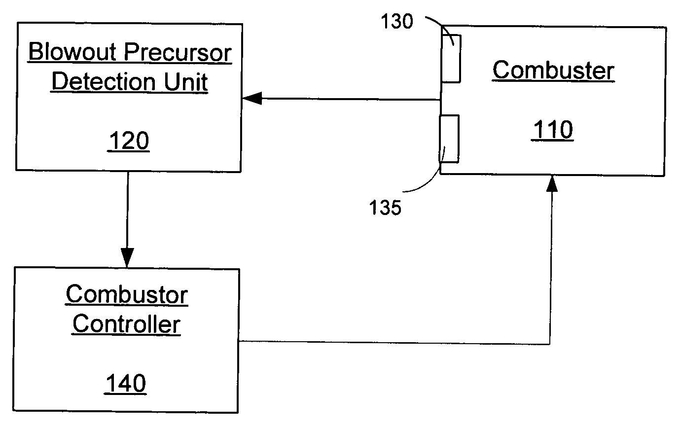
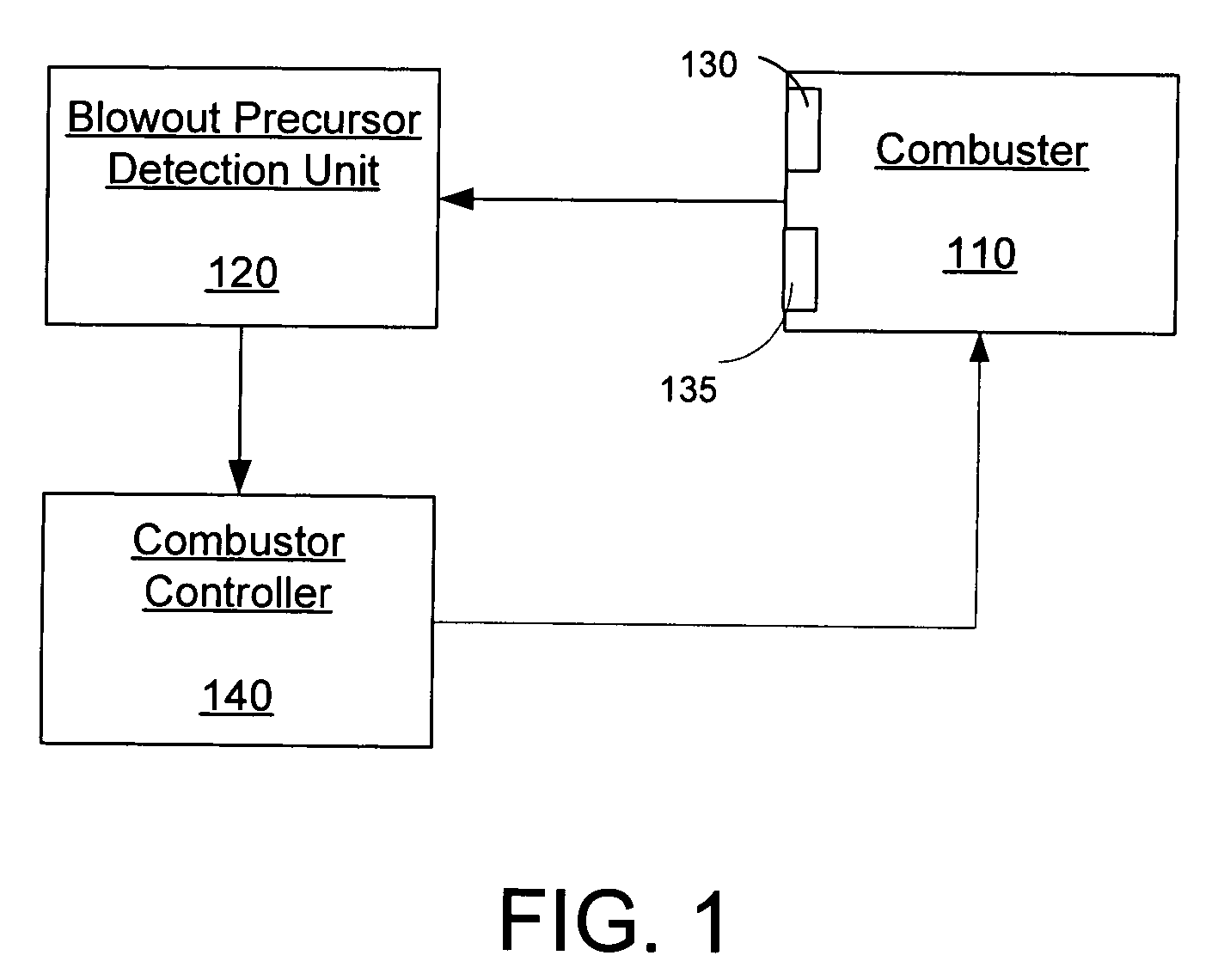
Yet another embodiment of the present invention is a method of controlling a combustor based on at least one combustor condition including the steps of acquiring at least one combustion condition from the combustor, wherein the combustor includes a fuel-air intake, determining the existence of a blowout precursor event based on the at least one combustor condition; and increasing the fuel flow in the fuel-air intake of the combustor in response to the identification of the existence of a blowout precursor event. The method may use combustor conditions including an acoustic pressure signal, an optical signal, or both. The method may further decrease the fuel flow in the fuel-air intake of the combustor in response to not identifying the existence of a blowout precursor event.

Problems solved by technology

The problem of blowout has long limited the allowable flow velocities through engines, particularly in systems such as gas turbines and afterburners which must operate at high flow rates and / or low pressures.
The problem of blowout, however, has become increasingly more severe in a range of combustion devices, as they are required to meet stringent emissions legislation, severe operability constraints, and achieve better performance.
The problem of flame blowout can occur in combustors of land-based turbine engines, aeronautical turbine engines, afterburners, industrial processing devices, or any other combustor device.
The trade-off, however, is an increased likelihood of blowing out of the flame.
In the land-based systems, a blow out event requires a potentially lengthy system shut down and restart, resulting in economic consequences to the power plant owner when blowout is encountered.
In the aeronautical setting, blowout is a particular concern during fast engine transients, such as when rapid acceleration or deceleration of the engine is attempted.
However, because of the magnitude of the possible consequences, engine designers include substantial safety margins into the engines to avoid these events, often at the cost of reduced performance in other areas.
The need to avoid blowout in combustors often causes designers to sacrifice performance in other areas.
In particular, because there is always some uncertainty in the exact conditions under which blowout may occur, extra margin must be built into the design.
However, the methods rely on monitoring absolute magnitudes of the pressure signal, which may change on other engines, at different power settings, or due to inherent variability in pressure, temperature, or humidity of the air.
Thus, the methods employed by Snyder are not robust and seemingly are operable only on the particular type of combustor tested and only under certain operating conditions.
The methods taught by Snyder are not expansive to different combustor types operating in a wide array of environmental conditions.
But no system or method exists in the industry that implements a closed-loop control system to actively change parameters in the combustor on a real time basis to prevent flame blowout based upon knowledge of the flame's stability characteristics.

Method used


Image

  • Systems and methods for detection and control of blowout precursors in combustors using acoustical and optical sensing
  • Systems and methods for detection and control of blowout precursors in combustors using acoustical and optical sensing
  • Systems and methods for detection and control of blowout precursors in combustors using acoustical and optical sensing

Examples


Embodiment Construction

The present invention now will be described more fully hereinafter with reference to the accompanying drawings, in which preferred embodiments of the invention are shown. This invention may, however, be embodied in many different forms and should not be construed as limited to the embodiments set forth herein; rather, these embodiments are provided so that this disclosure will be thorough and complete, and will fully convey the scope of the invention to those skilled in the art.

The present invention is described below with reference to block diagrams and flowchart illustrations of systems, methods, apparatuses and computer program products according to an embodiment of the invention. It will be understood that each block of the block diagrams and flowchart illustrations, and combinations of blocks in the block diagrams and flowchart illustrations, respectively, can be implemented by computer program instructions. These computer program instructions may be loaded onto a general pu...


PUM


Abstract

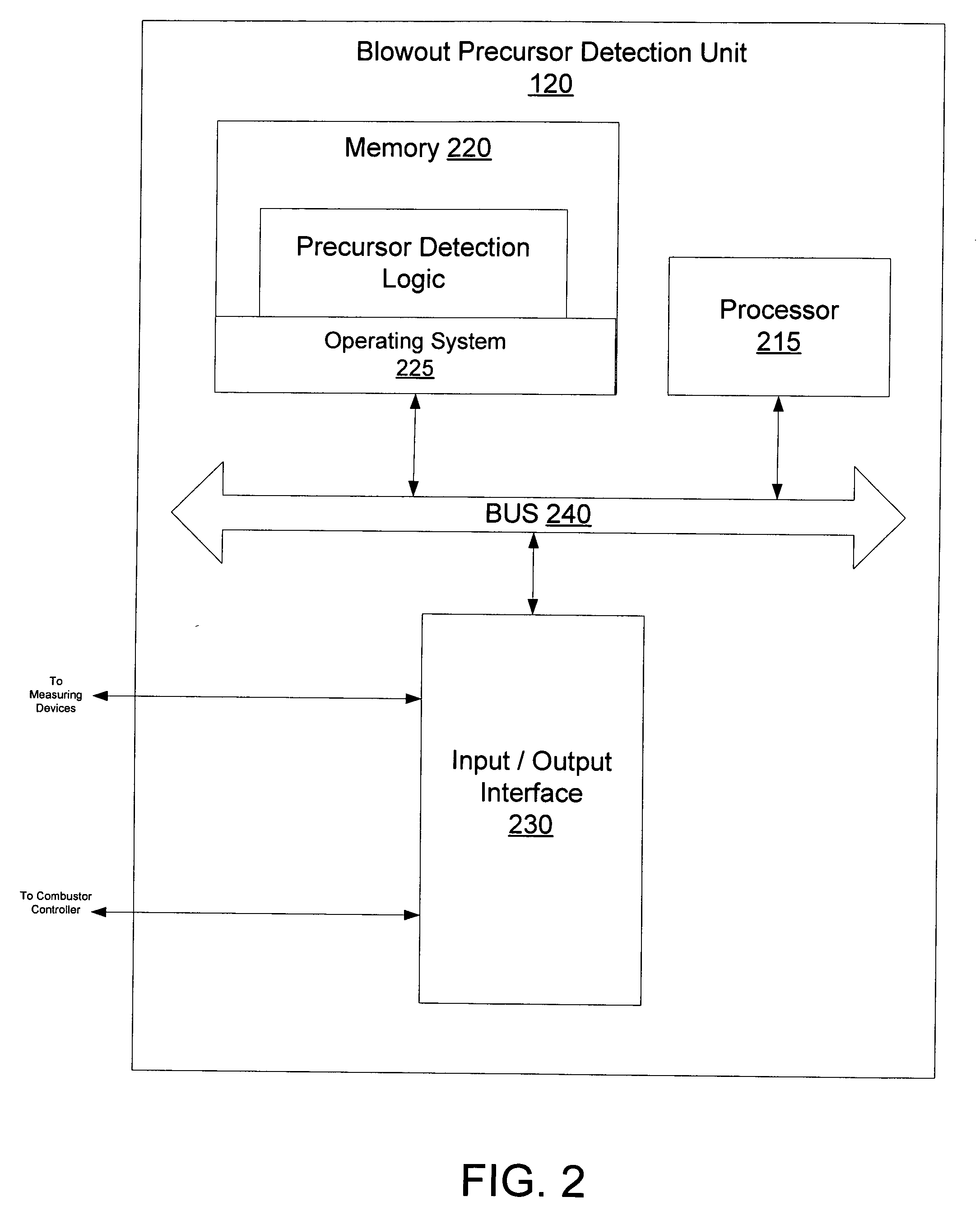
The present invention comprises methods for detecting and controlling flame blowout in combustors. The blowout precursor detection system comprises a combustor, a blowout precursor detection unit, a pressure measuring device and / or an optical measuring device. The methods of the present invention comprise receiving optical data measured by an optical measuring device, performing one or a combination of raw data analysis, spectral analysis, statistical analysis, and wavelet analysis on received optical data, and determining the existence of a blowout precursor based on such analyses. The present invention further comprises closed-loop control methods for controlling a combustor to prevent blowout.

Description

TECHNICAL FIELD This invention relates to combustors in gas turbine engines, afterburners, industrial processing devices, and other combustor devices and more particularly, to detection and control of blowout precursors in such combustors. BACKGROUND OF THE INVENTION Combustors have long been used to burn a fuel / air mixture that is ultimately used to generate thrust, produce power, supply heat for some industrial process, or other applications. In these systems, an important performance metric is for the flame to remain stably in the combustor over a range of flow rates, pressures, and fuel / air ratios. At certain conditions, however, the flame may “blow out” of the combustor, so that no flame exists. The problem of blowout has long limited the allowable flow velocities through engines, particularly in systems such as gas turbines and afterburners which must operate at high flow rates and / or low pressures. The problem of blowout, however, has become increasingly more severe in a ra...

Claims


Application Information

Patent Timeline
Patent Type & Authority Applications(United States)
IPC IPC(8): F23D14/72F23M11/04F23N5/24
CPCF23D14/725F23N2029/04F23N5/242F23M11/045F23N2229/04
Inventor LIEUWEN, TIM C.NAIR, SURAJTHIRUCHENGODE, MURUGANANDAMZINN, BEN T.NEUMEIER, YEDIDDIASEITZMAN, JERRYSCARBOROUGH, DAVID
Owner GEORGIA TECH RES CORP
Why Eureka
Try Eureka