
Device for damping pressure pulsations and a hydraulic unit equipped with this device

a technology of damping pressure and pulsation, which is applied in the direction of mechanical equipment, pipeline systems, transportation and packaging, etc., can solve the problems of total failure of the brake system, damage to the components of the hydraulic unit, and inability to accept the pressure increase, etc., to achieve good damping properties, simple to perform, and space-saving and economical effects

Active Publication Date: 2005-03-17
ROBERT BOSCH GMBH
View PDF5 Cites 3 Cited by
  • Summary
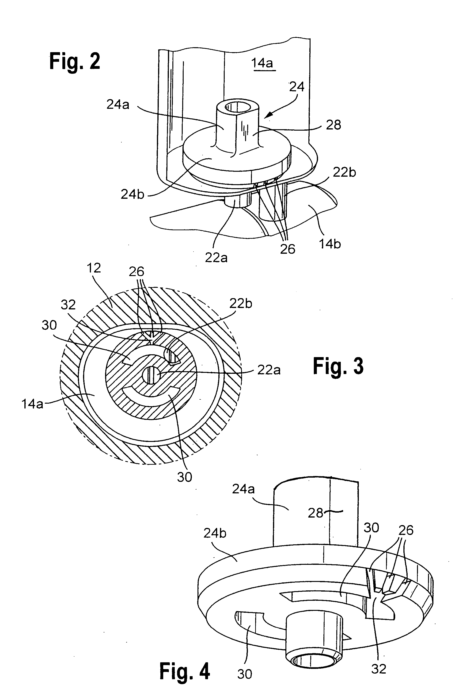
  • Abstract
  • Description
  • Claims
  • Application Information

AI Technical Summary

Benefits of technology

[0006] With the above background, it is the object of the present invention to provide both a device for damping pressure pulsations and a hydraulic unit equipped with this device, which preclude these disadvantages and, with a design that is as space-saving and economical as possible, have especially good damping properties.
[0007] The proposed device for damping pressure pulsations includes a function element, in which the throttle and the filter are combined in a single component. This function element can be anchored in the interior of a housing of the damping device, in a single work step that is simple to perform. It can be produced without metal-cutting machining and hence economically, preferably by injection molding from plastic. By means of a filter preceding the throttle, clogging of the throttle by dirt contained in the pressure fluid is averted. Otherwise, a clogged throttle could cause an impermissible pressure increase that could damage the components in the hydraulic unit. In an extreme case, the pressure increase could even cause leaks of the hydraulic unit and thus could lead to total failure of the brake system. An orientation aid can be mounted on the proposed device. With this orientation aid, the device can be oriented in a targeted way during the assembly process. With the orientation of the function element, additional prevention of an accumulation of air bubbles in the device is achieved. Since air bubbles can cause a reduction in the braking power, they are especially critical to function. Moreover, air that has already invaded the brake system can be eliminated again by a process of scavenging with pressure fluid.

Problems solved by technology

Otherwise, a clogged throttle could cause an impermissible pressure increase that could damage the components in the hydraulic unit.
In an extreme case, the pressure increase could even cause leaks of the hydraulic unit and thus could lead to total failure of the brake system.

Method used


Image

  • Device for damping pressure pulsations and a hydraulic unit equipped with this device
  • Device for damping pressure pulsations and a hydraulic unit equipped with this device
  • Device for damping pressure pulsations and a hydraulic unit equipped with this device

Examples


Embodiment Construction

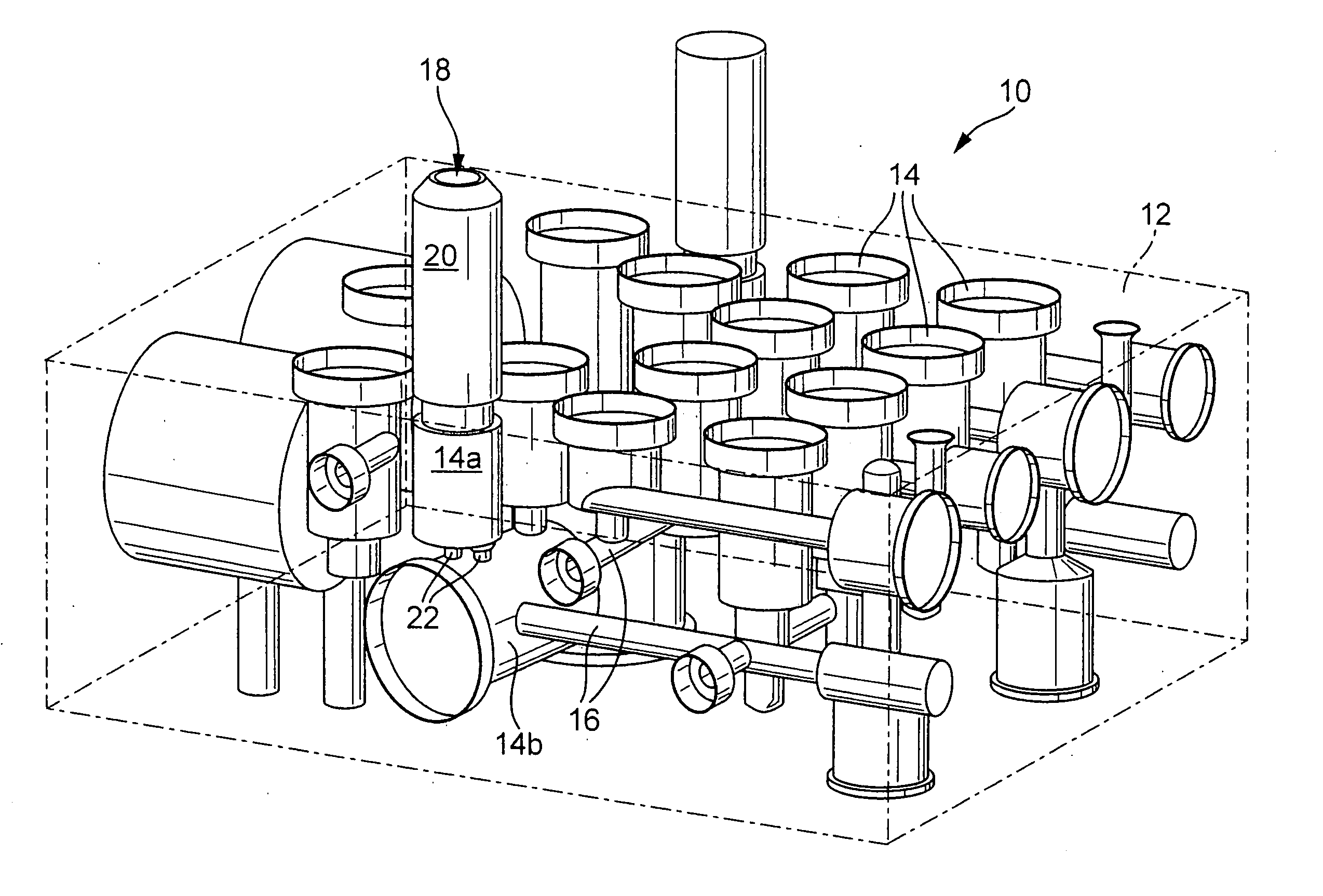
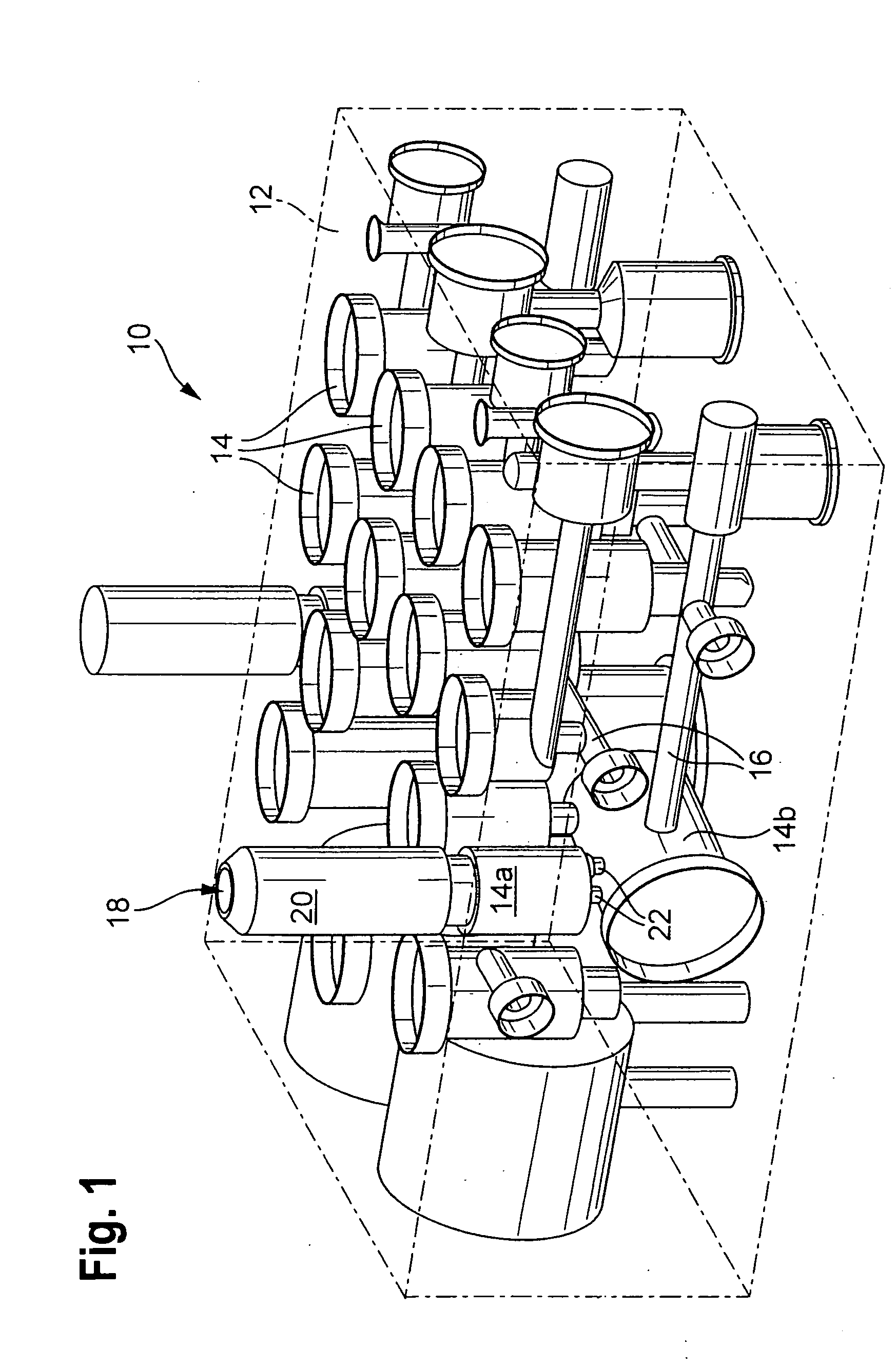
[0013]FIG. 1 shows a housing block 12 of a hydraulic unit 10 of an electronically regulatable vehicle brake system in which the block 12 is formed by a metal body, preferably produced by extrusion, which is machined by metal-cutting techniques to form the most various kinds of installation chambers 14. The installation chambers 14 are intended in particular to receive electronically triggerable magnet valves, pump elements, at least one drive element for these pump elements, pressure reservoirs, connections for brake lines, or devices for damping pressure pulsations. Moreover, pressure fluid conduits 16 are embodied in the housing block 12, which connect these various components hydraulically with one another for converting the hydraulic circuit of the vehicle brake system.

[0014] The installation chambers 14 are open toward at least one outer side of the housing block 12 and, together with the pressure fluid conduits 16 are oriented essentially at right angles to one another. This ...


PUM


Abstract

Pressure pulsations are damped in and a hydraulic unit by a device including a housing with an inlet and an outlet having a throttle and a filter preceding the throttle. The filter and the throttle are combined into a one-piece function element, which can be produced without metal-cutting machining and which can be fixed in the interior of the housing. This preceding filter prevents clogging of the throttle by contaminants in the pressure fluid, without requiring additional expense for parts or assembly. The function element can be produced economically in a minimum number of work steps, can be manipulated without problems, and in an advantageous refinement makes it possible to avoid unwanted accumulations of air in the device.

Description

BACKGROUND OF THE INVENTION [0001] 1. Field of the Invention [0002] The invention relates to a device for damping pressure pulsations, and a hydraulic unit equipped with this device, in an electronically regulatable vehicle brake system. For regulating the brake pressure required at the wheel brake cylinders, electronically regulatable vehicle brake systems require pump elements, which are acted upon as needed by a rotating drive element. This action is effected cyclically, and as a result, pressure pulsations can occur in the hydraulic circuit connected to it during the regulation cycle. The pressure pulsations can be transmitted to the brake pedal via the master cylinder located in the hydraulic circuit. The consequence is unwanted pulsating motions of this brake pedal as well as noise that is perceptible in the vehicle interior. [0003] 2. Description of the Prior Art [0004] For damping the pressure pulsations in an electronically regulatable brake system, a device is already know...

Claims


Application Information

Patent Timeline
IPC IPC(8): B60T17/04F15B21/041F15D1/02F16L55/04
CPCF15B21/041F15B21/008Y10T137/87885
Inventor SCHLITZKUS, MICHAELWEH, ANDREAS
Owner ROBERT BOSCH GMBH
Learn More