Radiation detection apparatus

a radiation detection and apparatus technology, applied in the field of apparatus and methods for measuring the radiation emitted from a radiation source, can solve the problems of significant time required for making these measurements, the method of beam scanning, and the error of the measured beam profile, so as to reduce the potential for radiation damage to the signal processor and the display, reduce the diameter of the interconnecting cable, and facilitate the use.

Inactive Publication Date: 2005-03-17
STANDARD IMAGING
View PDF6 Cites 40 Cited by
  • Summary
  • Abstract
  • Description
  • Claims
  • Application Information

AI Technical Summary

Benefits of technology

[0019] In a preferred embodiment, the detectors are separated from the signal processor and display by a distance sufficient to be positioned away from the direct radiation beam, greatly reducing the potential for radiation damage to the signal processor and the display. In one specific embodiment, a cable is provided that allows the signal processor to be situated away from the radiat...

Problems solved by technology

This method of beam scanning also has several limitations and drawbacks.
One limitation concerns the measurement of dynamic radiation treatment modalities, such as wedge-shaped radiation dose distribution (“dynamic wedge”) or intensity modulated radiation therapy (IMRT), in which the radiation intensity and/or beam profile changes over time.
Variations in the beam profile or intensity during the time needed to scan the beam result in errors in the measured beam profiles.
A significant amount of time is generally required to make these measurements, which can become tedious.
Further, operating a radiotherapy source for such extended time periods may also place undue stress on the source's and detector's components.
In addition, setting up and taking down a water tank and/or other beam scanning device can also be very time consuming and inconvenient.
The limitations and disadvantages of this method result from the number of locations in the beam that must be sampled and the small size of the detectors required in order to generate an image of the beam profile with suitable spatial resolution.
In that scheme, however, radiation strikes both the detectors and the electronics, resulting in damage to the electronics that occurs with accumulated radiation dose....

Method used


Image

  • Radiation detection apparatus
  • Radiation detection apparatus
  • Radiation detection apparatus

Examples


Embodiment Construction

[0033] For the purposes of promoting an understanding of the principles of the invention, reference will now be made to the embodiments illustrated in the drawings and specific language will be used to describe the same. It will nevertheless be understood that no limitation of the scope of the invention is thereby intended, such alterations and further modifications in the illustrated device, and such further applications of the principles of the invention as illustrated therein, being contemplated as would normally occur to one skilled in the art to which the invention relates.

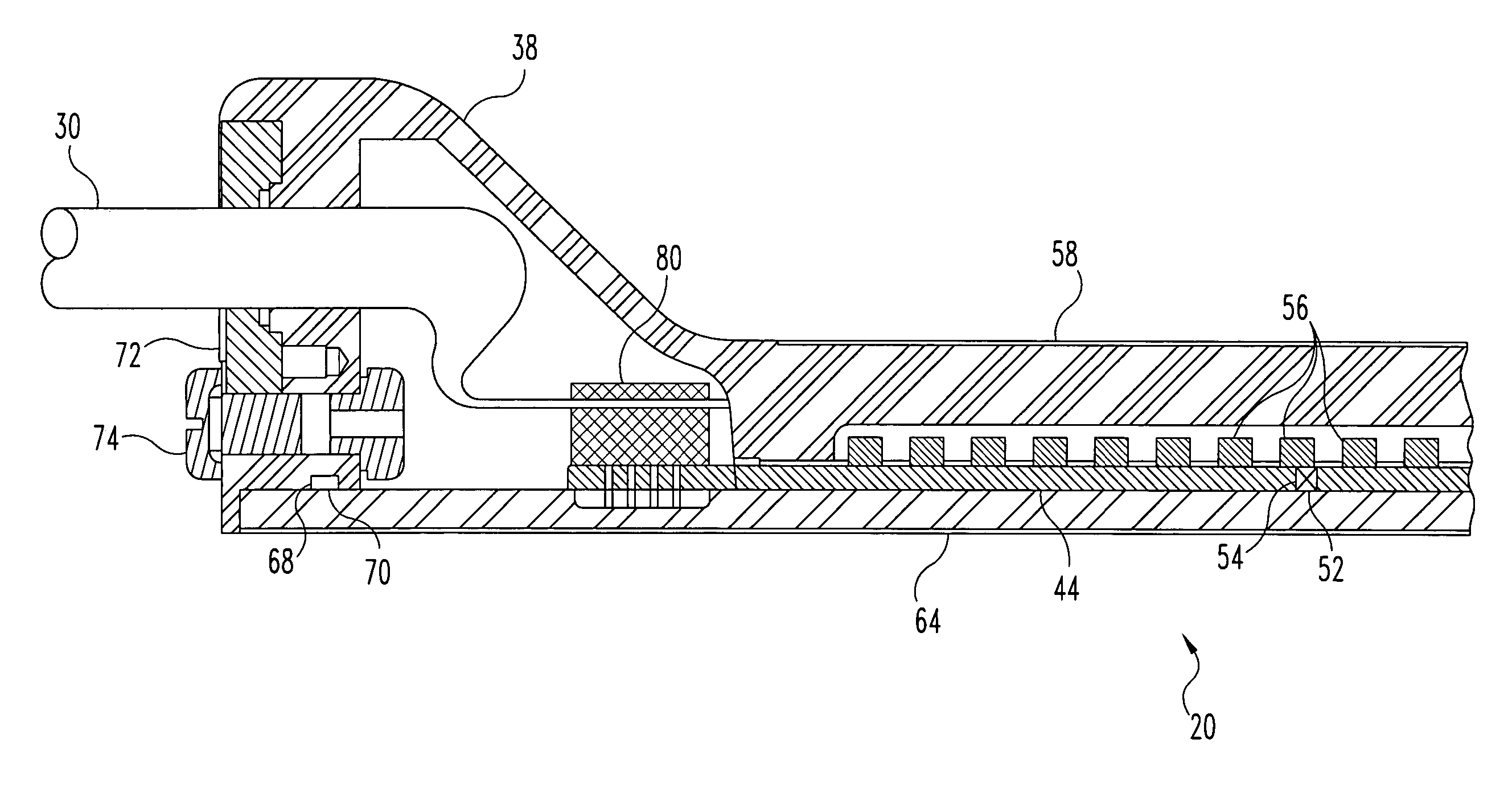
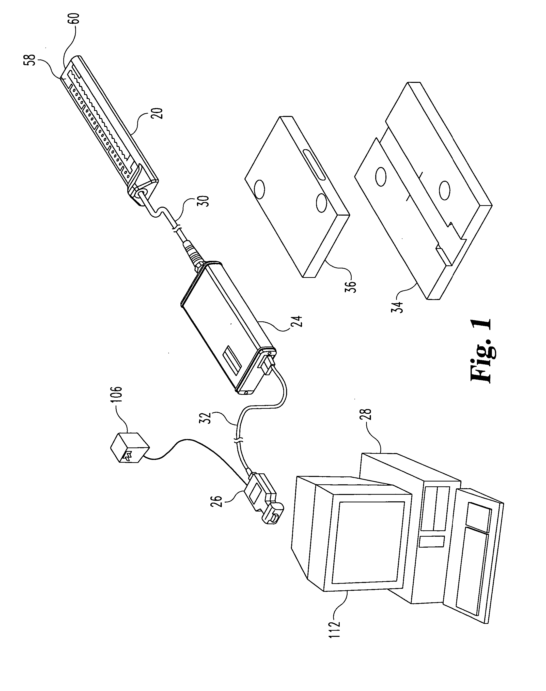
[0034] Referring generally to FIG. 1, an embodiment of a radiation detection system is shown, including an array 20 of radiation detectors 22, a signal processor 24, and an interface 26 that connects to a controller 28 (which may be a personal computer). Array 20 is connected to signal processor 24 via multi-conductor shielded cable 30, and in a specific embodiment the connection between array 20 and signal ...


PUM

PropertyMeasurementUnit
Electrical conductivityaaaaaaaaaa
Flexibilityaaaaaaaaaa
aaaaaaaaaa

Abstract

A radiation detection system has a linear array of radiation detectors, which are preferably ionization chambers. The detectors are connected, preferably permanently, to a multi-channel signal processor through a flexible multi-conductor shielded cable. The multi-channel signal processor is connected to a controller, such as a personal computer, through a multi-conductor cable and a communication interface device. Multiple detector arrays and multi-channel electrometers may be connected to a single personal computer and used simultaneously.

Description

FIELD OF THE INVENTION [0001] This invention concerns apparatus and methods for measuring the radiation emitted from a radiation source. In particular, the invention concerns an array of radiation detectors electronically linked to processing software and display apparatus for detecting the radiation emitted from medical radiation therapy sources. BACKGROUND OF THE INVENTION [0002] Radiation therapy treats tumorous tissue by delivering a prescribed lethal dose of high-energy radiation to the tumorous tissue. The dose and the placement of the dose must be accurately controlled to insure both that the tumor receives sufficient radiation to be destroyed and that damage to the surrounding and adjacent non-tumorous tissue is minimized. One type of such therapy, known as external-beam radiation therapy, uses a radiation source that is external to the patient. The source is typically either a radioisotope, such as cobalt-60, or a high-energy x-ray or electron source, such as a linear accel...

Claims


Application Information

Patent Timeline
IPC IPC(8): A61N5/10G01J1/42G01T1/00G01T1/16G01T1/17G01T1/185G01T1/24
CPCG01T1/244A61N5/1048
Inventor DONAGHUE, DAVID M.WHITE, ROBERT L.ZIMMERMANN, LEONARD W.
Owner STANDARD IMAGING
Why Eureka
Try Eureka