
Mixing apparatus

a technology of mixing apparatus and mixing chamber, which is applied in the direction of mixers, fuel gas production, water/sludge/sewage treatment, etc., can solve the problems of algae growth, unsuitable use, and usually unsuitable use, and achieve high air flow rate, reduce choking, and improve the effect of water flow ra

Inactive Publication Date: 2005-03-17
WYNES ANTHONY G
View PDF28 Cites 3 Cited by
  • Summary
  • Abstract
  • Description
  • Claims
  • Application Information

AI Technical Summary

Benefits of technology

[0006] One particular interest is in achieving a high degree of liquid movement and mixing in relation to the volume and pressure of gas injected. Another aim is to provide a simple and strong construction.
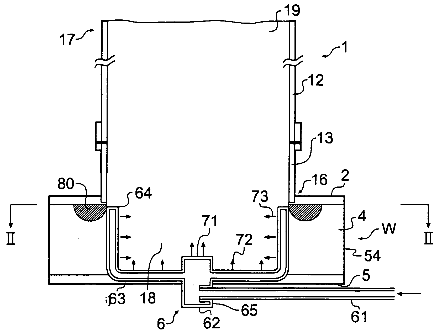
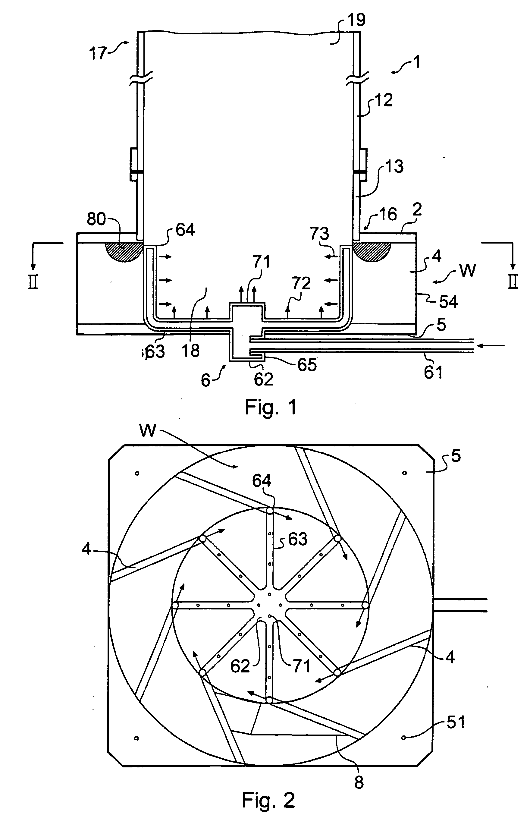
[0010] To create a flow, a gas injector arrangement is provided for injecting gas, e.g. compressed air, preferably at least at or adjacent to the foot of the draft tube. Preferably this means comprises an area array of jets, distributed over and preferably around the base region of the tube. Preferably an array of jets is distributed circumferentially in relation to the draft tube, on the draft tube's interior wall and / or below that level, e.g. at the level of the vanes. These injector nozzles are preferably directed obliquely relative to the radial direction so as to induce or follow rotation around the tube axis, although when vanes are provided as proposed above this is not essential. A large number of relatively small jets is found to be better than a few large air pipe outlets (where the large bubbles mix poorly), and better than a “bubble block” of permeable material which makes highly dispersible microbubbles but requires a high pressure. Preferably there are at least 10, more preferably at least 20 jets. Preferably each jet is not greater than 2 mm or 3 mm across. For economy, preferably the loss of head at the jets is not more than about 0.5 bar, more preferably not more than about 0.3 bar. Alternatively or additionally, the bubble size in the use of the device is preferably not more than about 10 mm (initial size, at the intake end). Larger bubbles entrain water less effectively and reduce the buoyancy of the rising plume.
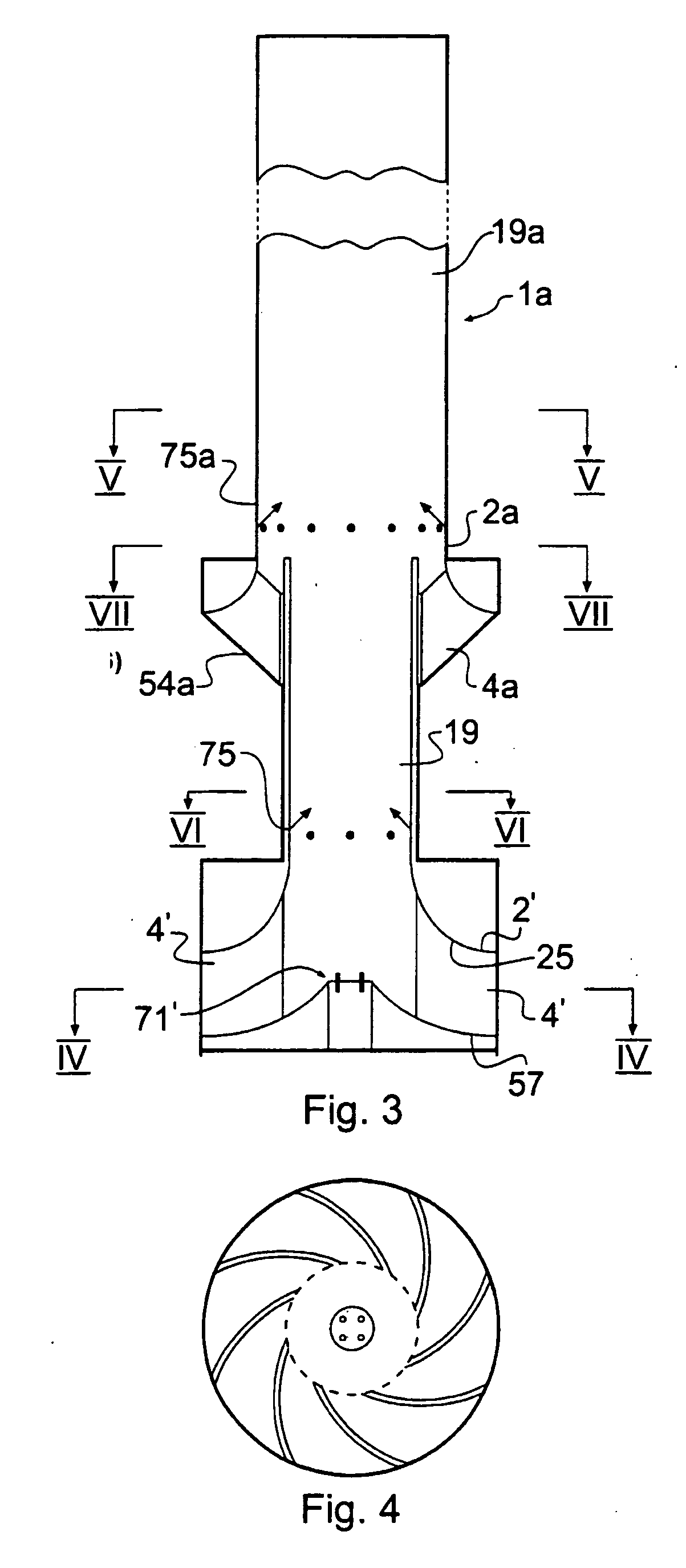
[0015] An optional enhancement of the system is to form the draft tube with upper and lower stages, the top of the lower draft tube leading into the base of the upper draft tube with a liquid input opening between them. This liquid input opening may be a full-circumference opening e.g. with a set of vanes which may have any one or more of the features recited above for the first vane arrangement. Particularly preferable is that the upper draft tube has a larger diameter than the lower. This is found to give enhanced water flow rate at high air flow rates, i.e. reduce choking, compared with a single stage set-up. Furthermore the upper draft tube may have its own set or sets of gas injection jets, e.g. distributed circumferentially or in any other arrangement as proposed above.

Problems solved by technology

Particularly where there is little or no natural flow or circulation, such large bodies of water are liable to certain difficulties which can render them unfit for use unless special measures are taken.
It is usually not fit for use.
This is a problem in a reservoir if the level falls.
Another issue is the growth of algae, particularly blue-green algae, which is an undesirable presence in reservoirs and flourishes at certain levels in still water, particularly the sunlit surface layers where it consumes oxygen (“BOD”).
The sea is likewise prone to stratification, despite tidal flows, e.g. there can be problems for fish farms and shellfish farms when concentrations of undesirable organisms such as algae arise near or are carried into the farm zone in a stable stratum.
However it is difficult to make, and the air bubbles tend to be large and to follow the shortest path up the helix without mixing with the water.
In the waste treatment field, many gasification apparatus are described using rotating impellers or paddles to drive mixing between liquid and gas, but the need for a mechanical drive in situ makes these expensive and limited in their field of use.

Method used


Image

  • Mixing apparatus
  • Mixing apparatus
  • Mixing apparatus

Examples


Embodiment Construction

[0027] With reference to FIGS. 1 and 2, a mixing / aerating apparatus has an upright cylindrical draft tube 1 open at its upper (exit) and lower ends 17,16. The material of the tube 1 is not critical; it may be of metal or plastics depending on circumstances. In this embodiment the internal diameter of the tube is 600 mm. The performance of the device in terms of water flow varies in a predictable manner according to the length of the draft tube and the depth of water. Typically the length is from 1 or 2 to 3 or 4 m for use in mixing liquid layers e.g. in a reservoir. For waste treatment it may be shorter, in accordance with the available depth of liquid. The bottom (intake) end 16 of the draft tube 1 is joined to a flat annular ring plate 2 which projects radially outwardly from the base of the tube. For convenience of transporting the device, in practice a short tube stump section 13 is bonded or welded into the opening of the ring plate 2 and then in a separate step screwed or bond...


PUM

PropertyMeasurementUnit
angleaaaaaaaaaa
radiusaaaaaaaaaa
radiusaaaaaaaaaa

Abstract

Mixing apparatus is disclosed suitable for the mixing and / or aeration of large bodies of water e.g. lakes or reservoirs. One particular use is in causing controlled destratification. Another area of use is in the aeration or oxygenation of liquid waste. The mixing apparatus has a draft tube (1) with an open interior, and gas injectors (6) to drive an upward flow of liquid through the draft tube (1). An arrangement of angled vanes (4) at the intake of the draft tube imposes swirl on the flow, which then rises unobstructed through the draft tube (1). No moving parts are involved.

Description

FIELD OF THE INVENTION [0001] This invention has to do with apparatus and methods for causing mixing in bodies of liquid using gas bubbles. A primary aspect is to do with causing mixing in large bodies of water such as ponds, lakes, reservoirs or indeed the sea, where usually the mixing of the liquid is important. Another aspect is to do with gasification in liquid treatment plants, e.g. for sewage or other waste treatment, where usually the mixing of gas is important. BACKGROUND [0002] There are circumstances in which it is important to be able to mix bubbles of air or other gas into a body of liquid in order to treat it. One well-known instance is waste water treatment. Industrial effluents and sewage need aeration. Less well known but of great importance is the treatment or aid to natural regeneration of large static water supplies, such as rivers, lakes and reservoirs. Particularly where there is little or no natural flow or circulation, such large bodies of water are liable to ...

Claims


Application Information

Patent Timeline
Patent Type & Authority Applications(United States)
IPC IPC(8): B01F3/04B01F15/00B01F15/02
CPCB01F3/0446B01F3/04517B01F15/0201B01F15/00525B01F15/005B01F23/232B01F23/232311B01F35/32015B01F35/3203B01F35/712B01F35/7179
Inventor WYNES, ANTHONY G.
Owner WYNES ANTHONY G
Learn More