System to control the luminosity and extend the life of motor vehicle lights

a technology of luminosity and motor vehicle lights, applied in vehicle headlamps, electric lighting sources, transportation and packaging, etc., can solve the problems of destroying light filaments, affecting and affecting the operation of motor vehicle lights, so as to facilitate the alteration of luminosity levels and prolong the life of motor vehicle lights

Inactive Publication Date: 2005-03-17
KOVER JOSEPH JR +1
View PDF0 Cites 22 Cited by
  • Summary
  • Abstract
  • Description
  • Claims
  • Application Information

AI Technical Summary

Benefits of technology

[0005] Furthermore, the application of the present invention can also be collectively extended to prolong the life of the motor vehicle lights with the exception of the turn signal lights and emergency flasher lights. The majority of the motor vehicle lights fail during the initial power up phase. The reason for these failures is because during the power up phase, when the light filament is cold, the impedance is considerably less than a light filament that has attained a normal operating temperature. Consequently, the initial surge current through a cold light filament is significantly greater than the current through a light filament that has attained a normal operating temperature. Accordingly the surge currents that occur during the initial power up phase weaken and eventually destroy the light filament. The present invention also serves to eliminate the detrimental current surges and the transients that are introduced during the initial power up phase and during the load-switching phase.
[0006] The preferred embodiment of the system to control the luminosity and extend the life of the motor vehicle lights is comprised of a digital sequencing device, a drive circuit device, and a current/voltage limiting device such as bipolar transistors or metal oxide semiconductor field effect transistors. In addition the embodiment also includes a means to measure the DC current through the motor vehicle lights and the adverse weather rear lights and/or the DC voltage across the motor vehicle lights and the adverse weather rear lights to negate the normalized on resistance versus temperature characteristics of the current/voltage control devices and the varying impedance of the light source, which is disadvantageous in applications where the luminosity of motor vehicle lights operate at a reduced luminous level. In the reduce

Problems solved by technology

The majority of the motor vehicle lights fail during the initial power up phase.
The reason for these failures is because during the power up phase, when the light filament is cold, the impedance is considerably less than a light filament that has attained a normal operating temperature.
Accordingly the surge currents that occur during the initial power up phase weaken and eventually destroy the light filament.
In addition the embodiment also includes a means to

Method used


Image

  • System to control the luminosity and extend the life of motor vehicle lights
  • System to control the luminosity and extend the life of motor vehicle lights
  • System to control the luminosity and extend the life of motor vehicle lights

Examples


Embodiment Construction

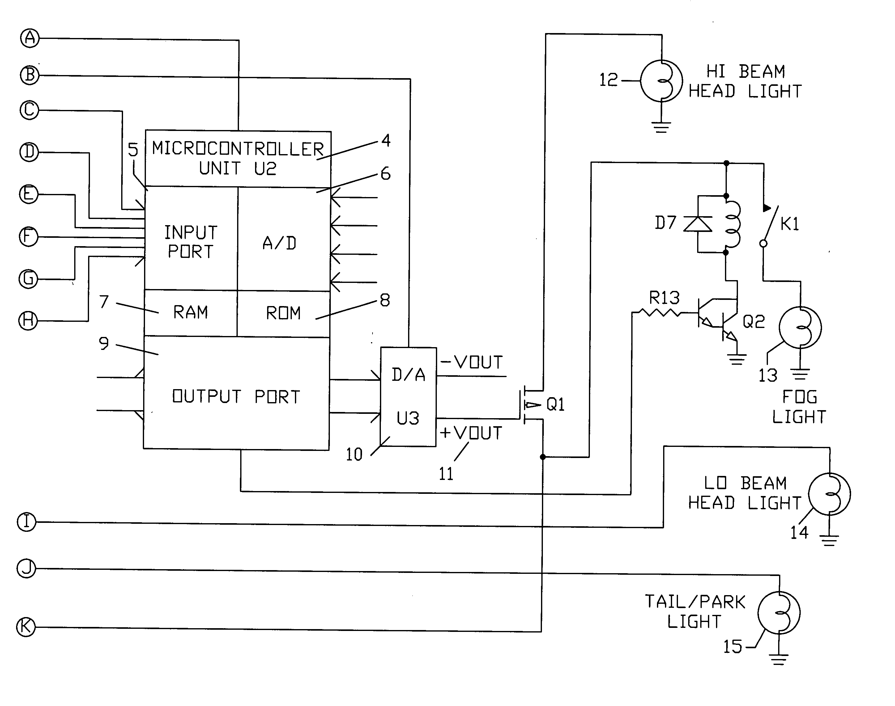
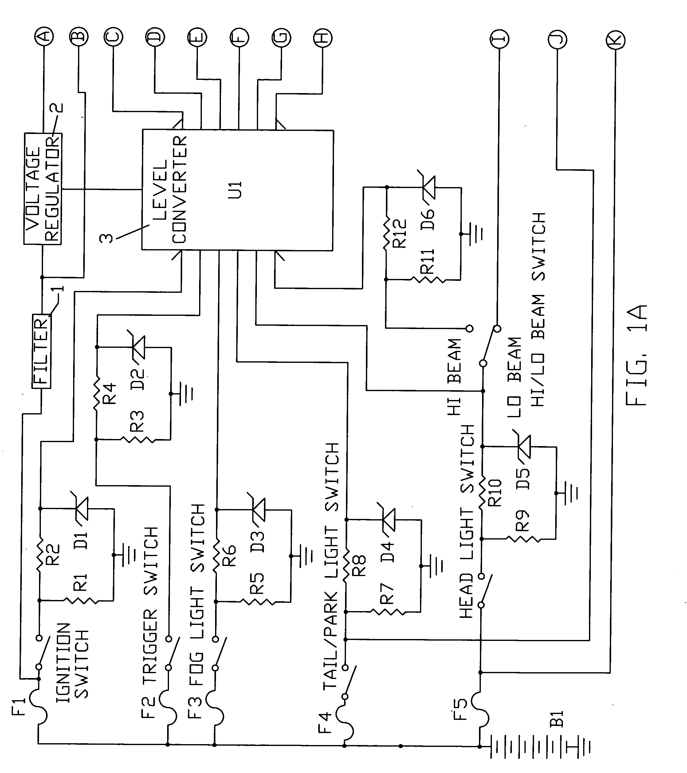
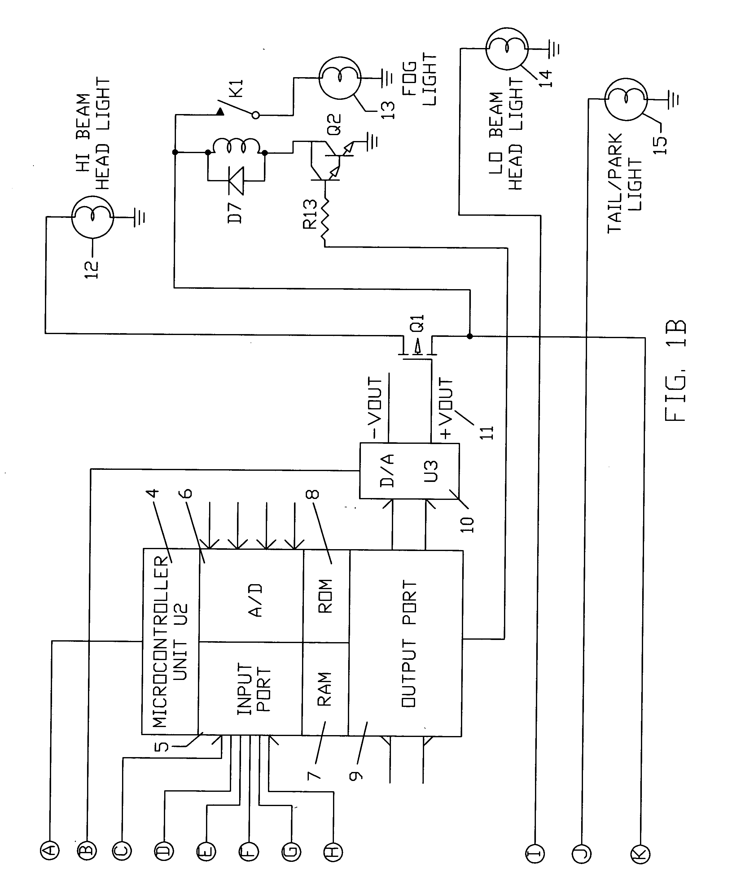
[0029] The drawings shown in FIGS. 1A, 1B, 2A, 2B, 3, 4, 5, 6A through 6C, 7A through 7G, 8, 9A, and 9B for the preferred embodiments of the system to control the luminosity and extend the life of the motor vehicle lights will now be addressed in complete detail.

[0030]FIG. 1A is the schematic diagram, according to the present invention, that illustrates the vehicle battery B1, the inputs to the logic level down converter 3 which are comprised of the motor vehicle headlight switch, the high beam headlight switch, the trigger switch (the park brake switch or the transmission park / neutral safety switch), the fog light switch, the tail / park light switch, the ignition switch, and the corresponding fuses that protect the vehicle electrical system from an over current condition. Furthermore, additional inputs, such as the windshield wiper switch may be included to further establish the state of the vehicle. FIG. 1A further illustrates the reversed battery and over voltage protection circu...


PUM


Abstract

The present invention relates to a system to control the luminosity and extend the life of the motor vehicle lghts. The present invention can further be extended to where the motor vehicle lights are progressively increased as the current ambient light conditions or the current visibility conditions decrease and progressively decreased as the current ambient light conditions or the current visibility conditions.

Description

BACKGROUND OF THE INVENTION [0001] The present invention relates to a system that controls the luminosity and extends the life of the motor vehicle lights. The application to control the luminosity of the motor vehicle headlights is widely used where the conventional headlights serve in a dual capacity. During the hours from dawn to dusk the headlights operate in the daytime running light mode, at a reduced luminous level, whereas during the hours from dusk to dawn the headlights operate in the normal mode, at the full luminous level. This application can further be extended to where the motor vehicle lights are progressively increased as the current ambient light conditions or the current visibility conditions decrease and progressively decreased as the current ambient light conditions or the current visibility conditions increase. The application can also be extended to include the rear fog lights during low visibility conditions. [0002] Furthermore, the application of the present...

Claims


Application Information

Patent Timeline
IPC IPC(8): B60Q1/14B60Q1/26
CPCB60Q1/1423B60Q1/2603B60Q2400/30B60Q2300/314B60Q2300/312
Inventor KOVER, JOSEPH JR.KOVER, JOSEPH DAVID
Owner KOVER JOSEPH JR
Why Eureka
Try Eureka