Refrigerating cycle apparatus, air conditioning apparatus, throttle device and flow controller

Inactive Publication Date: 2005-03-24
MITSUBISHI ELECTRIC CORP
View PDF10 Cites 18 Cited by
  • Summary
  • Abstract
  • Description
  • Claims
  • Application Information

AI Technical Summary

Benefits of technology

[0009] An object of the present invention, which was made to solve the above problems, is to provide a refrigerating cycle apparatus and an air conditioning apparatus using a throttle device and a flow controller that can greatly reduce refrigerant flow noise and are not clogged by foreign materials in a cycle. Another object of the present invention is to provide a low noise and reliable refrigerating cycle apparatus. Another object of the present invention is to provide a low noise throttle device and flow controller. Another object of the present invention is to provide a reliable throttle device and flow controller that are not clogged by foreign materials. Another object of the present invention is to provide a less expensive apparatus having

Problems solved by technology

However, when the number of rotations of the compressor is reduced in a cooling operation, an evaporating temperature also increases, thus a problem arises in that the dehumidifying capacity of an evaporator is reduced or an evaporating temperature exceeds the dew point temperature in a room and dehumidification cannot be executed.
In the conventional air conditioning apparatuses as described above, since a flow control valve having an orifice is usually used as the second flow control valve disposed in an indoor unit, large refrigerant flow noise is produced when the refrigerant passes through the orifice and the indoor environment is deteriorated thereby.
In particular, since the inlet of the second flow control valve is filled with a gas/liquid two-phase refrigerant in the dehumidifying operation, a problem arises in that the refrigerant flow noise is increased.
However, there is a problem that this arrangement is not effective because the number of flow paths that can be disposed from processing point view is limited and the refrigerant flow

Method used


Image

  • Refrigerating cycle apparatus, air conditioning apparatus, throttle device and flow controller
  • Refrigerating cycle apparatus, air conditioning apparatus, throttle device and flow controller
  • Refrigerating cycle apparatus, air conditioning apparatus, throttle device and flow controller

Examples


Example

[0111] Embodiment 1

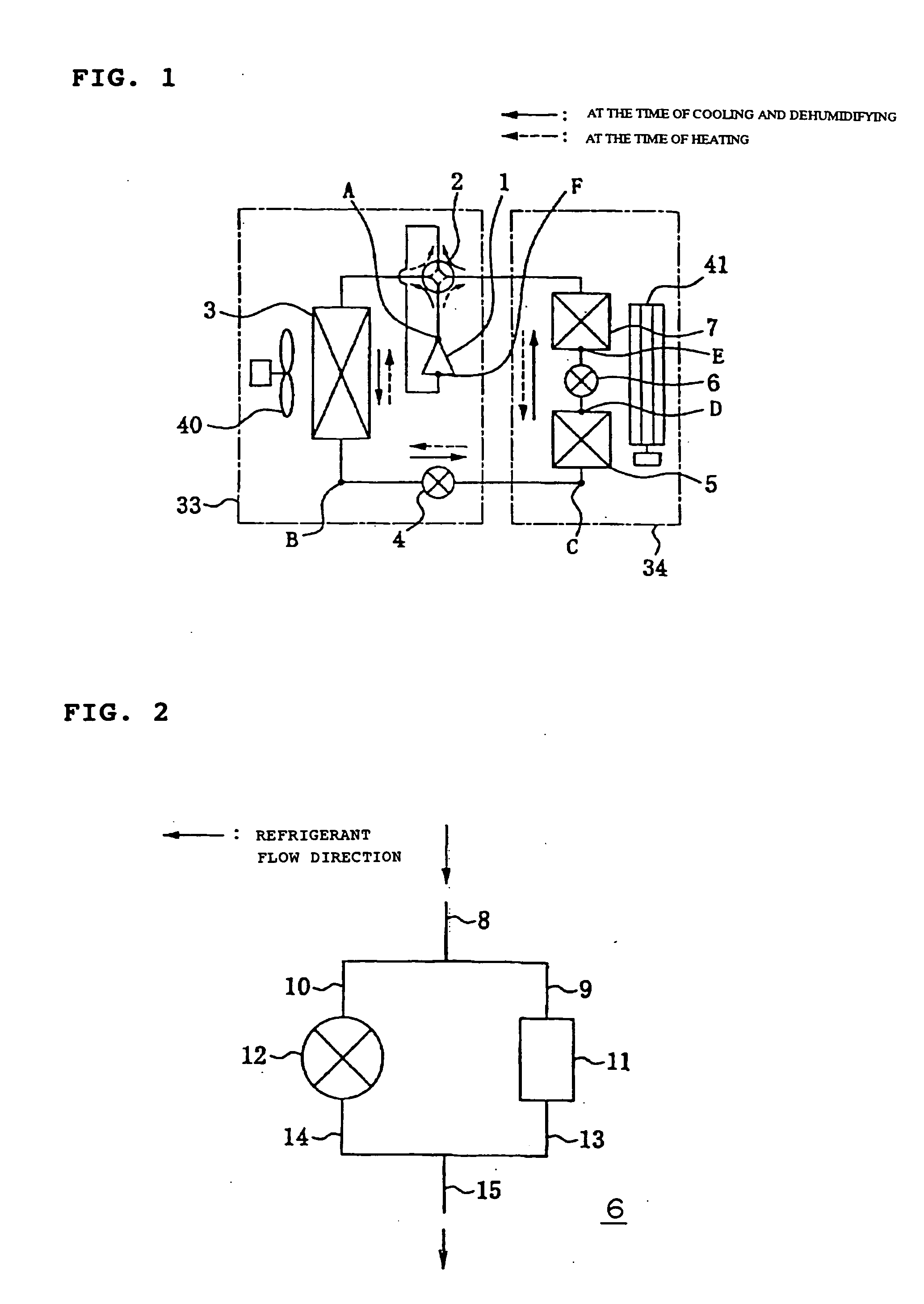
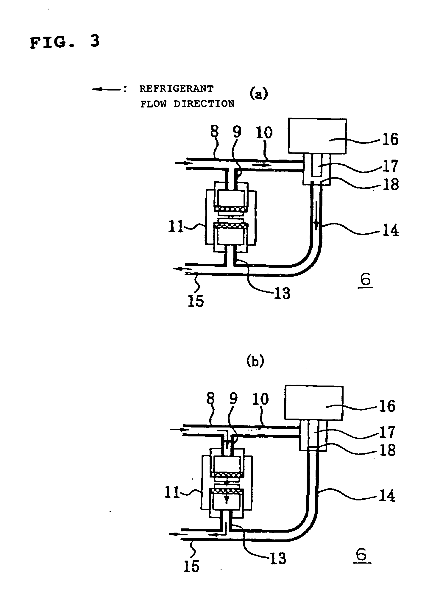
[0112]FIG. 1 is a refrigerant circuit diagram of an air conditioning apparatus showing an example of an embodiment of the present invention, wherein the same components as those of the conventional apparatus are denoted by the same reference numerals. In the figure, numeral 1 denotes a compressor, 2 denotes a flow-path switching means, for example, a 4-way valve for switching a refrigerant flow between a cooling operation and a heating operation, 3 denotes an outdoor heat exchanger, 4 denotes a first flow controller, 5 denotes a first indoor heat exchanger, 6 denotes a second flow controller, and 7 denotes a second indoor heat exchanger, and these components are sequentially connected to each other through pipes and constitute a refrigerating cycle. Further, an outdoor unit 33 contains an outdoor fan 40 attached to the outdoor heat exchanger 3, and an indoor unit 34 contains an indoor fan 41 attached to the two indoor heat exchangers. A mixed refrigerant R410A co...

Example

[0221] Embodiment 2

[0222] In the embodiment 1, the structure of the second flow controller has been mainly described with reference to the examples of the throttle device used in parallel with the multi-directional valve and to the applied examples thereof. In the second embodiment, however, the structure of a throttle device integral with a valve will be described. Accordingly, in the following description, the operation of a refrigerating cycle and the operation and arrangement of an air conditioning apparatus are the same as those of the embodiment 1 except the portions having specific structures. A multi-directional valve is assembled to the throttle device integrally therewith, or it is examined to arrange them more compact so as to obtain a throttle device and a flow controller that are smaller in size and lighter in weight.

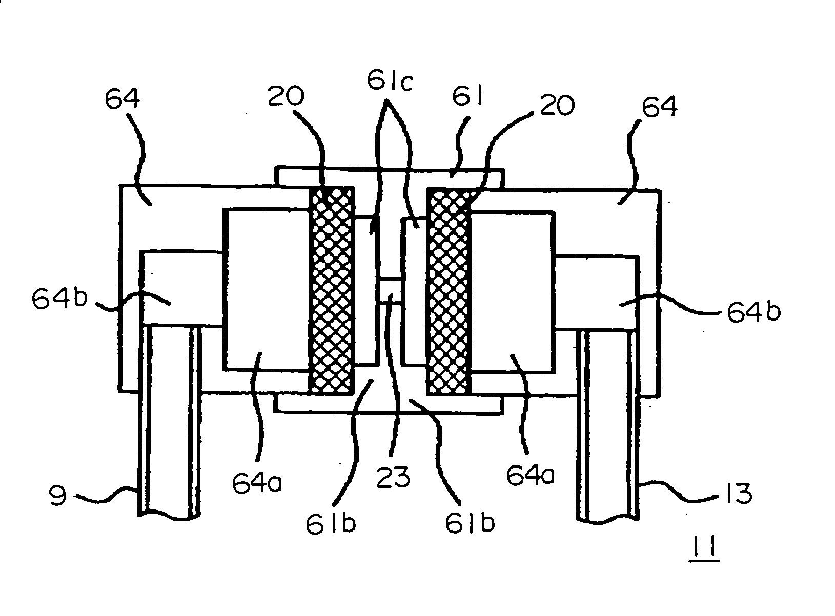
[0223]FIG. 55 is a sectional view showing the arrangement of the second flow controller of the air conditioning apparatus shown in FIG. 1. In the figure,...


PUM


Abstract

In a refrigerating cycle incorporating a second flow controller having a throttle section, which is composed of an inlet noise eliminating space 19, an inlet side porous permeable member 20 communicating in a refrigerant flow direction, an orifice 23, an outlet side foamed metal 25, and an outlet noise eliminating space 27, and a multi-directional valve, a gas/liquid two-phase refrigerant is caused to pass through the throttle section.

Description

BACKGROUND ART [0001] The present invention relates to a refrigerating cycle apparatus that has a throttle structure suitable to control a refrigerant flow and that is suitable to control a two-phase refrigerant, and further relates to an air conditioning apparatus that improves temperature and humidity controllability in a cooling or heating operation, reduces refrigerant flow noise, and improves comfort with respect to room temperature and humidity and noise. Further, the present invention relates to a low noise throttle device or a low noise flow controller that has a simple structure and high reliability and reduces fluid flow noise. [0002] Conventional air conditioning apparatuses use a variable capacitance type compressor such as an inverter, and the like to cope with the fluctuations of an air conditioning load, and the rotational frequency of the compressor is controlled according to the magnitude of the air conditioning load. However, when the number of rotations of the com...

Claims


Application Information

Patent Timeline
IPC IPC(8): F25B13/00F25B41/06F25B43/00
CPCF25B13/00F25B41/06F25B41/062F25B41/067F25B43/003F25B2313/02341G05D7/0647F25B2313/02344F25B2341/0662F25B2400/0411F25B2500/12F25B2500/26F25B2700/02F25B2313/02343F25B41/39F25B41/35Y02B30/70
Inventor HIRAKUNI, SATOSHISUMIDA, YOSHIHIROMAKINO, HIROAKIMOCHIDUKI, ATUSHIONISHI, SHIGEKITANABE, YOSHIHIRO
Owner MITSUBISHI ELECTRIC CORP
Why Eureka
Try Eureka