Sensors and systems for structural health monitoring

a sensor and system technology, applied in the field of structural health monitoring, can solve the problems of inability to implement a reliable sensory network system, inability to accommodate a large number of actuator arrays, time-consuming and expensive, etc., to achieve accurate identification technique, improve durability, and improve reliability and maintainability.

Inactive Publication Date: 2005-03-24
ADVANCED STRUCTURE MONITORING
View PDF9 Cites 76 Cited by
  • Summary
  • Abstract
  • Description
  • Claims
  • Application Information

AI Technical Summary

Benefits of technology

[0011] Accordingly, it is one object of the invention to provide an improved structural health monitoring system that comprises network patches and data acquisition unit for the diagnosis, classification and prognosis of structural conditions.
[0012] It is another object of the invention to provide patches that operate as actuators and/or sensors and comprise multilayer-coated piezoceramic disks and/or optical fiber loops.
[0013] It is still another object of the invention to provide a diagnostic sensory system having enhanced reliability and maintainability without modifying or dismantling its host struc...

Problems solved by technology

Although still used for inspection of isolated locations, they are time-consuming and expensive.
However, these approaches have drawbacks and may not provide effective on-line methods to implement a reliable sensory network system and/or accurate monitoring methods that can diagnose, classify and forecast structural condition with the minimum intervention of human operators.
A drawback of this system is that it cannot accommodate a large number of actuator arrays and, as a consequence, each of actuators and sensors must be placed individually.
Since the damage detection is based on the changes of vibrational waves traveling along the line-of-sight paths between the actuators and sensors, this method fails to detect the damage located out of the paths and/or around the boundary of the structure.
A drawback of these passive methods is that they cannot monitor internal delamination and damages between the sensors.
As a conseque...

Method used


Image

  • Sensors and systems for structural health monitoring
  • Sensors and systems for structural health monitoring
  • Sensors and systems for structural health monitoring

Examples


embodiment 180

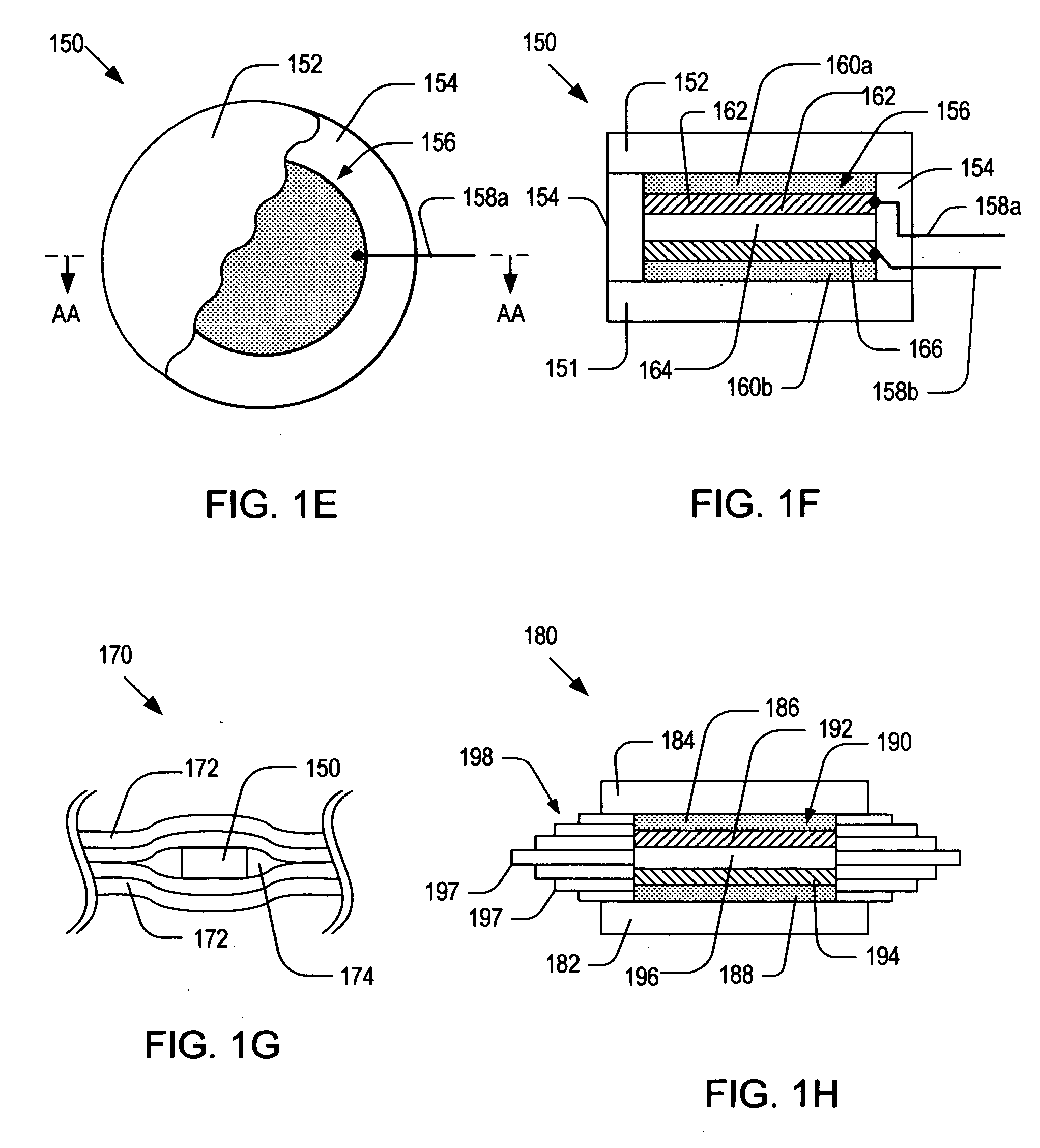
[0075]FIG. 1H is a schematic side cross-sectional view of an alternative embodiment 180 of the patch sensor 150 of FIG.1 E. As illustrated, the patch sensor 180 may include: a bottom substrate 182; a top substrate 184; a hoop layer 198; a piezoelectric device 190; top and bottom buffer layers 192 and 194; and the piezoelectric device 196. For simplicity, a pair of wires connected to the piezoelectric device 190 is not shown in FIG. 1H. The piezoelectric device 190 may include: a piezoelectric layer 196; a bottom conductive flake 194; and a top conductive flake 192. The functions and materials for the components of the patch sensor 180 may be similar to those of their counterparts of the patch sensor 150.

[0076] The hoop layer 198 may have one or more sublayers 197 of different dimensions so that the outer contour of the hoop layer 198 may match the geometry of cavity 174. By filling the cavity 174 with sublayers 197, the adhesive material may not be accumulated during the curing proc...

embodiment 318

[0089]FIG. 3C a schematic top cut-away view of the optical fiber coil 308 contained in the optical fiber patch sensor of FIG. 3A, illustrating a method for rolling the optical fiber cable 312. As shown in FIG. 3C, the outermost loop of the optical fiber coil 308 may start with one end 310a while the innermost loop may end with the other end 310b. FIG. 3D a schematic top cut-away view of an alternative embodiment 318 of the optical fiber coil 308 shown in FIG. 3C. As shown in FIG. 3D, the optical fiber cable 322 may be folded and rolled in such a manner that the outermost loops may start with both ends 320a-b. The rolled optical fiber cable 322 may be covered by a coating layer 319.

[0090] It is noted that the optical fiber coils 308 and 318 show in FIGS. 3C-D may be attached directly to a host structure and used as optical fiber coil sensors. For this reason, hereinafter, the terms “optical fiber coil” and “optical fiber coil sensor” will be used interchangeably. FIGS. 3E-F are alter...


PUM


Abstract

Sensors and systems for monitoring structural health conditions. The present invention provides a device for monitoring structural health conditions including a dielectric substrate, a piezoelectric device for actuating and/or sensing Lamb waves, a molding layer deposited over the piezoelectric device, a cover layer deposited over the molding layer and a hoop layer surrounding the piezoelectric device and being attached to the substrate. The device further includes an optical fiber coil sensor attached to the dielectric substrate, where the coil sensor has a rolled optical fiber cable and a coating layer applied to the rolled optical fiber cable. The present invention also provides a diagnostic patch network that includes a plurality of patch sensors attached to a host structure and a bridge box connected to the patch sensors. The bridge box sends information of structural health conditions to and receive power from a ground control system using a wireless communication technique.

Description

CROSS REFERENCE TO RELATED APPLICATIONS [0001] This application claims the benefit of U.S. Provisional Applications No. 60 / 505,120, entitled “sensor and system for structural health monitoring,” filed on Sep. 22, 2003, which is hereby incorporated herein by reference in its entirety.BACKGROUND OF THE INVENTION [0002] 1. Field of the Invention [0003] The present invention relates to diagnostics of structures, and more particularly to diagnostic network patch (DNP) systems for monitoring structural health conditions. [0004] 2. Discussion of the Related Art [0005] As all structures in service require appropriate inspection and maintenance, they should be monitored for their integrity and health condition to prolong their life or to prevent catastrophic failure. Apparently, the structural health monitoring has become an important topic in recent years. Numerous methods have been employed to identify fault or damage of structures, where these methods may include conventional visual inspe...

Claims


Application Information

Patent Timeline
IPC IPC(8): G01N29/04G01H9/00G01H11/00G01H11/08G01N21/88G01N29/06G01N29/07G01N29/22G01N29/24G01N29/28G01N29/44G21C17/00
CPCG01H9/004G01N2291/106G01H11/08G01M5/0033G01M5/0066G01M5/0091G01M11/086G01N29/043G01N29/0609G01N29/0672G01N29/07G01N29/223G01N29/245G01N29/2475G01N29/2493G01N29/28G01N29/4418G01N29/4463G01N2291/011G01N2291/015G01N2291/02491G01N2291/0258G01N2291/0422G01N2291/0423G01N2291/0427G01H11/00G01S15/88G06Q50/08
Inventor KIM, HYEUNG-YUN
Owner ADVANCED STRUCTURE MONITORING
Why Eureka
Try Eureka