Carbon nanotube manufacturing apparatus and method, and gas decomposer for use in the manufacturing apparatus and method

Inactive Publication Date: 2005-03-24
FUJIFILM BUSINESS INNOVATION CORP
View PDF9 Cites 21 Cited by
  • Summary
  • Abstract
  • Description
  • Claims
  • Application Information

AI Technical Summary

Benefits of technology

[0010] The present invention has been made in view of the above circumstances, and provides novel carbon nanotube manufacturing apparatus and method that offer a user a choice of using, or not using, a metal catalyst according to the user's need in vapor phase growth, whose

Problems solved by technology

While those attempts to develop carbon nanotube applications are being made, no technique has succeeded in manufacturing carbon nanotubes stably and efficiently.
This method is capable of manufacturing carbon nanotubes with few defects in molecule structure, but does not allow successive operation and therefore is low in productivity.
This method is suitable for manufacturing single-wall carbon nanotubes of high purity, but is low in productivity because of the methods small yield and inability to allow successive operation.
However, carbon nanotubes manufactured by any of these method

Method used


Image

  • Carbon nanotube manufacturing apparatus and method, and gas decomposer for use in the manufacturing apparatus and method
  • Carbon nanotube manufacturing apparatus and method, and gas decomposer for use in the manufacturing apparatus and method
  • Carbon nanotube manufacturing apparatus and method, and gas decomposer for use in the manufacturing apparatus and method

Examples


embodiment 1

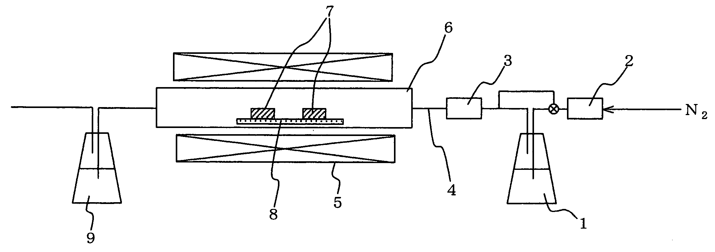
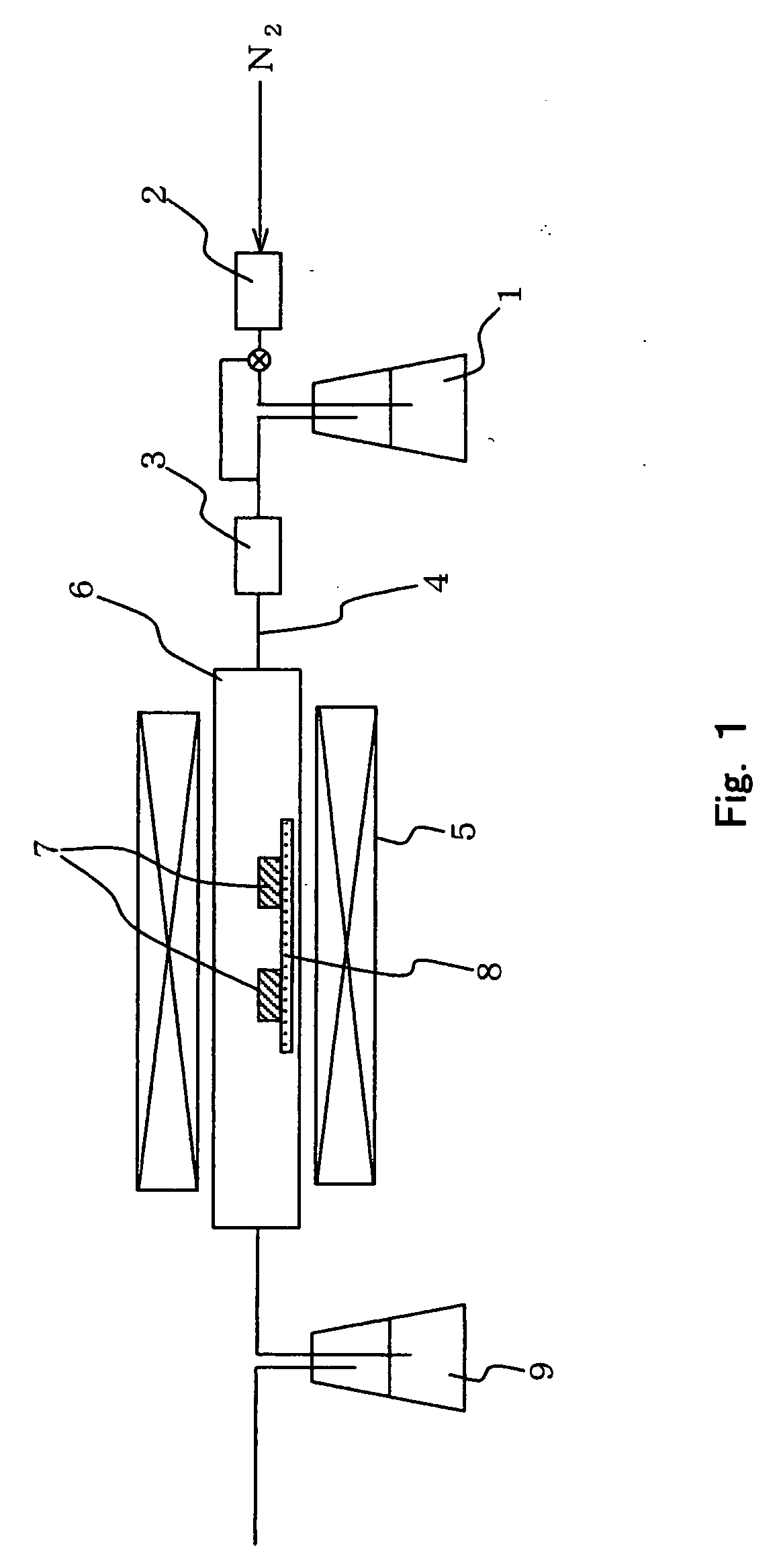
[0070]FIG. 1 is a schematic sectional view showing a manufacturing apparatus of Embodiment 1, which is an example of a carbon nanotube manufacturing apparatus of the present invention. Hereinafter, a carbon nanotube manufacturing apparatus may also be referred to as manufacturing apparatus. The manufacturing apparatus of this embodiment has the structure of Mode (1) and is used in the carbon nanotube manufacturing method (hereinafter may also be referred to as manufacturing method) of Mode .

[0071] The manufacturing apparatus shown in FIG. 1 is equipped with a raw material tank 1, a carrier gas flow rate adjuster 2, a raw material gas flow rate adjuster 3, a gas supplying pipe 4, a heating furnace (heating unit) 5, a reaction tube 6, a gas decomposer 7, a substrate (fixed portion) 8, and an exhaust trap 9.

[0072] The raw material tank 1 stores a carbon source for forming carbon nanotubes. The carbon source is mixed with a carrier to obtain a feeding gas that contains a raw material....

embodiment 2

[0100]FIG. 4 is a schematic sectional view showing a manufacturing apparatus of Embodiment 2, which is an example of a manufacturing apparatus of the present invention. The manufacturing apparatus of this embodiment has the structure of Mode (2) and is used in the manufacturing method of Mode .

[0101] The manufacturing apparatus of this embodiment is identical with that of Embodiment 1 except that this embodiment employs gas supplying pipes 14 and 14′ which are different in structure from the gas supplying pipe 4 and that the items placed in the reaction tube 6 are different in detail. Therefore, members of this embodiment and of Embodiment 1 that have identical functions are denoted by the same symbols as shown in FIGS. 1 and 4, and detailed descriptions on such members are omitted here.

[0102] As shown in FIG. 4, the manufacturing apparatus of this embodiment has the gas supplying pipe 14 communicated with the gas supplying pipe 14′, which has an inner diameter (15 mm) slightly la...

embodiment 3

[0106]FIG. 6 is a schematic sectional view showing a manufacturing apparatus of Embodiment 3, which is an example of a manufacturing apparatus of the present invention. The manufacturing apparatus of this embodiment has the structure of Mode (3) and is used in the manufacturing method of Mode .

[0107] The manufacturing apparatus of this embodiment is identical with that of Embodiment 1 except that the items placed in the reaction tube 6 are different in detail. Therefore, members of this embodiment and of Embodiment 1 that have identical functions are denoted by the same symbols as shown in FIGS. 1 and 6, and detailed descriptions on such members are omitted here.

[0108] As shown in FIG. 6, the manufacturing apparatus of this embodiment employs a gas decomposer 27, which is obtained by applying a gas decomposer material to an inner wall of the reaction tube 6. A substrate 28 made of alumina, similar to the substrate 8 of Embodiment 1, is placed on the inside of the gas decomposer 27...


PUM

PropertyMeasurementUnit
Angleaaaaaaaaaa
Flow rateaaaaaaaaaa
Circumferenceaaaaaaaaaa

Abstract

A gas decomposer formed from a porous material to decompose a carbon-containing raw material carried on a gas flow and to synthesize a carbon nanotube from the decomposed carbon-containing raw material is provided as a member suitable for use in carbon nanotube manufacture that offers a user a choice of using, or not using, a metal catalyst according to the user's need in vapor phase growth, which allows successive operation and which is therefore fit for mass production. Also provided are carbon nanotube manufacturing apparatus and method which use the gas decomposer.

Description

FIELD OF THE INVENTION AND RELATED ART STATEMENT [0001] The present invention relates to carbon nanotube manufacturing apparatus and method, particularly, carbon nanotube manufacturing apparatus and method capable of collecting carbon nanotubes more efficiently while employing vapor phase growth, which is high in manufacturing efficiency, and also relates to a member (gas decomposer) suitable for use in the manufacturing apparatus and method. [0002] Carbon structures represented by carbon nanotubes and fullerenes are lately being considered for applications in various fields because of their small sizes and unique properties. Carbon nanotubes, in particular, are a subject of many studies which try to put carbon nanotubes into practical use as emitters for field emission displays, as field effect transistors, as probes for scanning probe microscopes, as negative electrodes of lithium secondary batteries, and as various composite materials. [0003] While those attempts to develop carbo...

Claims


Application Information

Patent Timeline
IPC IPC(8): B01J15/00B01J19/24C01B31/02C23C16/00C23C16/26
CPCB01J15/005B01J19/2415B82Y30/00C01B2202/36C01B31/0233C01B2202/30C01B2202/34B82Y40/00C01B32/162
Inventor MIYAHARA, TOMOKOANAZAWA, KAZUNORIWATANABE, HIROYUKI
Owner FUJIFILM BUSINESS INNOVATION CORP
Why Eureka
Try Eureka