Liquid crystal display device

a liquid crystal display and display device technology, applied in liquid crystal compositions, instruments, chemistry apparatus and processes, etc., can solve the problem of not being able to disclose an art to optically modulate the transparent nematic phase, and achieve the effect of reducing the aperture rate, and fast response speed

Inactive Publication Date: 2005-03-24
SHARP KK
View PDF20 Cites 18 Cited by
  • Summary
  • Abstract
  • Description
  • Claims
  • Application Information

AI Technical Summary

Benefits of technology

tes is judiciously set so that the effect of the invention may be sufficiently exerted.
The liquid crystal layer mentioned above comprises a liquid crystalline material containing liquid crystal molecules and fine particles. The liquid crystal molecules and fine particles are both comprised of one or two or more species. Moreover, it is preferable to disperse the fine particles in the liquid crystalline material so that the liquid crystal layer may contain a dispersion of the fine particles. The liquid crystalline material may contain additives such as an optically active substance and a dichroic dye. That is, insofar as the effect of the present invention can be exerted, the liquid crystal layer prepared from said liquid crystalline material and fine particles may contain other components in addition to said liquid crystal molecules and fine particles.
The liquid crystal molecules mentioned above are not particularly restricted if they are capable of exhibiting liquid crystallinity, and for example, nematic liquid crystal molecules are preferred. The dielectric anisotropy (Δ∈) of the liquid crystalline material constituted by such liquid crystal molecules may be positive or negative but the use of a liquid crystalline material with a negative dielectric anisotropy is preferred to the use of a liquid crystalline material with a positive dielectric anisotropy because of faster response speed and higher aperture rate. This is because in the case where a liquid crystalline material with a positive dielectric anisotropy is used, the mode of changing a liquid crystal display by utilizing the movement of liquid crystal molecules in the lateral direction (minor-axis direction) is the preferred mode but since such mode is constitutionally equivalent to the IPS mode, the response speed is not sufficient and, because of the immobility of liquid crystal molecules on the electrode, the aperture rate may also possibly be insufficient.
The dielectric anisotropy (Δ∈) mentioned above can be calculated by the equation of Δ∈=∈1−∈2, wherein ∈1 represents the dielectric constant in the direction of the long axis of the liquid crystal molecule and ∈2 represents the dielectric constant in the direction of the minor axis of the liquid crystal molecule. The dielectric constant ∈ can be calculated by the equation of ∈=Cpd / S (wherein Cp represents the capacitance of the liquid crystal; d represents the thickness of the liquid crystal layer; S represents the area of the overlapping part of electrodes on two substrates) as described in Okano, Mitsuharu & Kobayashi, Shunsuke (ed.): “Liquid Crystals, Fundamentals” (K. K. Baifu-Kan, Jul. 15, 1985, p. 215 to 216).
The liquid crystal layer in the present invention is optically isotropic when the voltage applied to the electrode is lower than the threshold value and undergoes optical transition due to change in the arrangement of liquid crystal molecules when the applied voltage is not lower than the threshold value. The term “optically isotropic” used herein refers to a state in which optical properties are constant regardless of the direction of measurement or, in the case of a liquid crystalline material, a condition which is evaluated is equivalent to that state.
The above liquid crystal layer may be such that it is more optically isotropic in the case where the voltage applied to the electrode is lower than the threshold value as compared with the case in which the applied voltage is not lower than said threshold value and that when the applied voltage is not lower than the threshold value, the liquid crystal molecules are arranged in a predetermined direction to cause a change in the optically isotropic state and thereby change the liquid crystal display of the liquid crystal display device. In the present invention, it is preferable to set the case in which the voltage applied to the electrode is lower than the threshold value to be the state corresponding to no application of voltage to the electrode.

Problems solved by technology

However, although it is stated that, in such a liquid crystal microemulsion, the liquid crystals undergo phase transition in response to changes in temperature and concentration to form a transparent nematic phase, there is no disclosure of an art to optically modulate the transparent nematic phase.
Furthermore, in the formation of said emulsion (a), it is difficult to attain a microfine size and, moreover, many hours of standing results in separation of the transparent nematic phase and ceasing to maintain an emulsion state, so that there was room for further technical innovation.
However, these are not devices utilizing the characteristic of a transparent nematic phase that despite the nematic orientational orders are locally formed, an isotropic phase is macroscopically formed.
However, said characteristic of a transparent nematic phase is not used even in such a fine liquid crystal dispersion.

Method used


Image

  • Liquid crystal display device
  • Liquid crystal display device
  • Liquid crystal display device

Examples


example 1

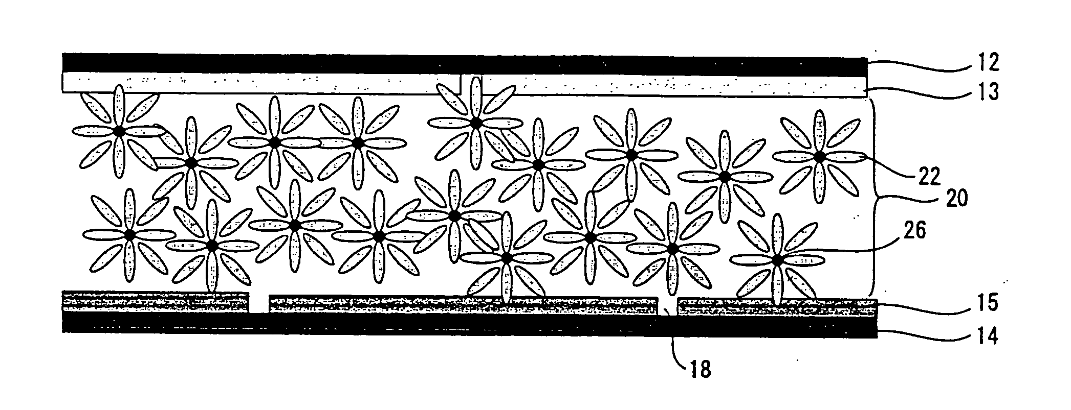
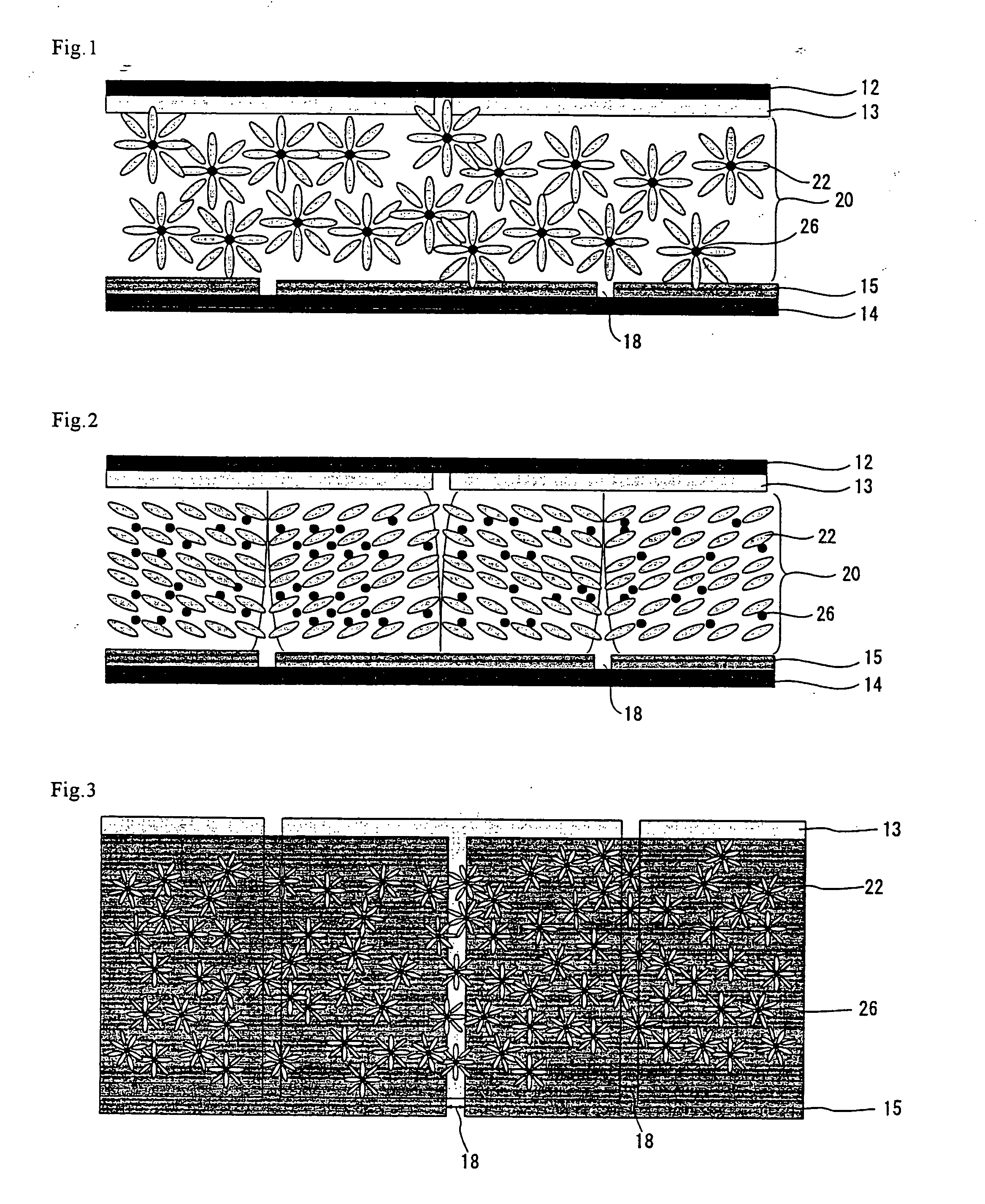
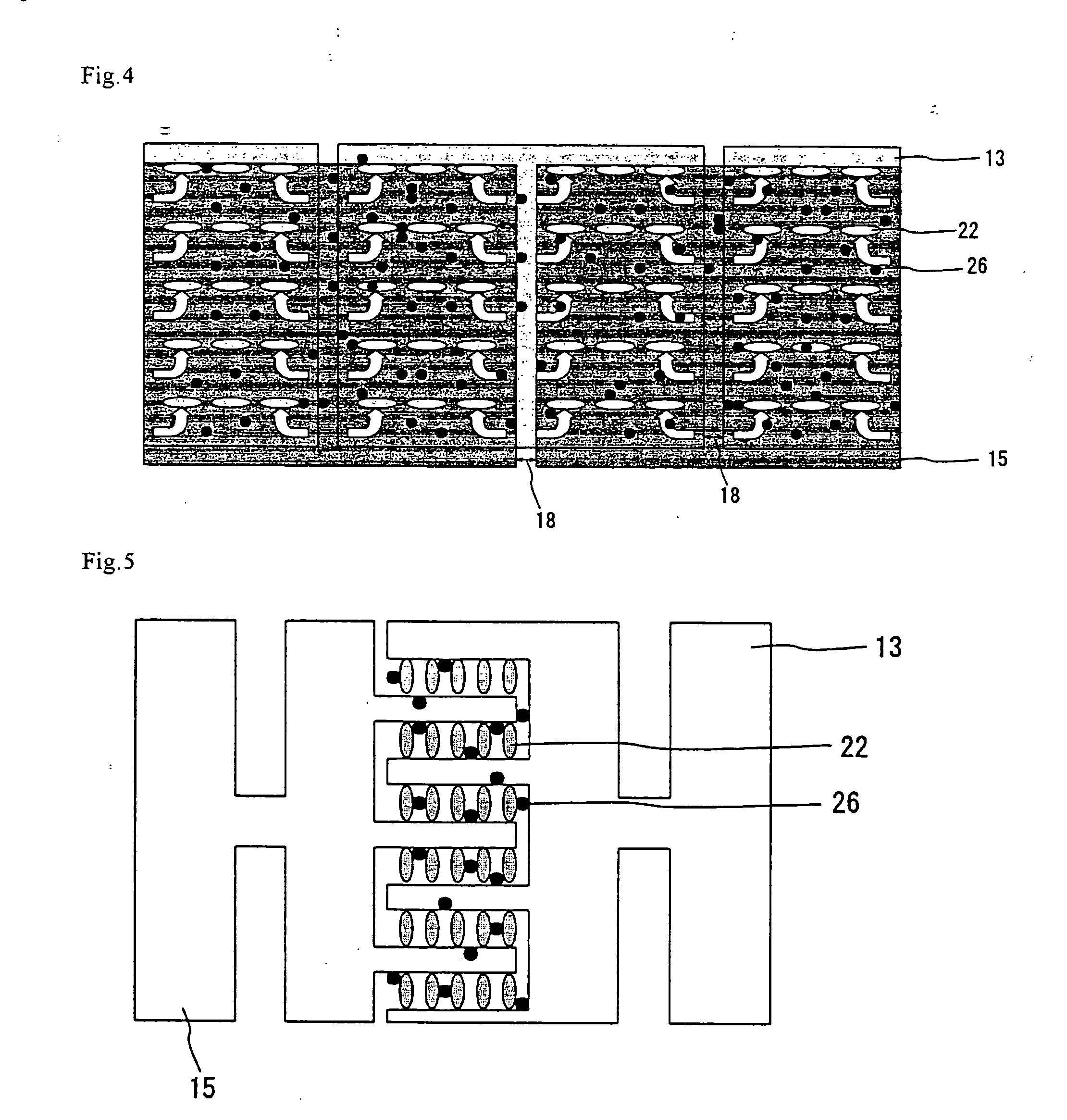
As the liquid crystalline material, MLC-2037 (product name; manufactured by Merck Ltd.) comprising nematic liquid crystal molecules and having a negative dielectric anisotropy, i.e. Δ∈<0, and as the fine particles, fullerene C60 of 99.9% by mass purity were used. The content of the fine particles (the mixing ratio of the fine particles) based on the total mass of the fine particles and liquid crystalline material was set to 5% by mass. This mixture was injected between the liquid crystal cells fabricated using glass substrates each provided with a transparent conductive layer having slits and sealed to produce a liquid crystal display device. The thickness of said liquid crystal cell was controlled to 5 μm. The liquid crystal cell was made to have the structure as shown in FIG. 1. In this fabrication process, the substrates were not subjected to aligning treatments such as deposition of an alignment layer or rubbing. When polarizing plates were arranged in cross nicol, the liq...

example 2

Except that the mixing ratio of the fine particles was changed to 15% by mass, a liquid crystal display device was fabricated in the same manner as Example 1, and the light transmittance was measured.

As a result, a sufficient contrast ratio was obtained as shown in Table 1.

Moreover, as in Example 1, the liquid crystal layer did not undergo phase separation even after being left for several days.

Furthermore, when the mixing ratio of the fine particles was changed, it was found that similar results can be obtained within the formulation range of 1 to 20% by mass.

This device can also be provided with a reflecting means to be used as a reflection mode device or a semi-transmission mode liquid crystal display device.

examples 3 and 4

Except that the mixing ratio of the fine particles was changed to 0.5% by mass and 30% by mass, liquid crystal devices were fabricated in the same manner as Examples 1 and 2, and the light transmittance of the respective devices were determined. The results are shown in Table 1.


PUM

PropertyMeasurementUnit
particle diameteraaaaaaaaaa
sizeaaaaaaaaaa
particle diametersaaaaaaaaaa

Abstract

It is an object of the present invention to provide a liquid crystal display device in which a liquid crystal layer may form a stable transparent state and, in addition, which provides for a black display with an excellent viewing angle characteristic, as well as a high contrast ratio and a high response speed in liquid crystal display. The present invention is directed to a liquid crystal display device comprising an electrode and a liquid crystal layer between substrates, said liquid crystal layer consists of a liquid crystalline material containing liquid crystal molecules and fine particles, and is optically isotropic when the voltage applied to the electrode is lower than a threshold value and undergoes optical transition due to change in the arrangement of the liquid crystal molecules when the applied voltage is not lower than the threshold value.

Description

FIELD OF THE INVENTION The present invention relates to a liquid crystal display device. More particularly, the invention relates to a liquid crystal display device comprising an electrode and a liquid crystal layer both being formed between a pair of spaced-apart substrates which are placed oppositely each other. DESCRIPTION OF THE RELATED ART The liquid crystal display device is a display means utilizing characteristics of liquid crystal molecules, and is in broad use for displaying information and images. The liquid crystal display device of the type which is most prevalently in use at the present time is TN-LCD (twisted nematic liquid crystal display). Above all else, the fabrication technology for TN-TFT (thin film transistor)-LCD has made a dramatic progress in recent years, even to the extent that the device today is surpassing the CRT (cathode-ray tube) in front contrast ratio and color reproducibility. In regard to liquid crystal display devices such as TN-LCD, there is a...

Claims


Application Information

Patent Timeline
Patent Type & Authority Applications(United States)
IPC IPC(8): G02F1/133G02F1/1334G02F1/139
CPCG02F1/1334G02F2201/124G02F1/139
Inventor NAKAMURA, MASAKOHASHIMOTO, YOSHITOSHINOMIYA, TOKIHIKOMIZUSHIMA, SHIGEAKI
Owner SHARP KK
Why Eureka
Try Eureka