Method for manufacturing a photoresist-coated glass board, method for manufacturing a stamper and method for manufacturing a recording medium

a technology of photoresist coating and manufacturing method, which is applied in the direction of photomechanical equipment, instruments, originals for photomechanical treatment, etc., can solve the problems of difficult to correctly read data recorded in the optical recording medium, the following defects of the conventional pit pattern forming method, and the difficulty of correct reading of data from the optical recording medium

a technology of photoresist coating and manufacturing method, which is applied in the direction of photomechanical equipment, instruments, originals for photomechanical treatment, etc., can solve the problems of difficult to correctly read data recorded in the optical recording medium, the following defects of the conventional pit pattern forming method, and the difficulty of correct reading of data from the optical recording medium

US20050064345A1Inactive Publication Date: 2005-03-24TDK CORPARATION

Image

  • Method for manufacturing a photoresist-coated glass board, method for manufacturing a stamper and method for manufacturing a recording medium
  • Method for manufacturing a photoresist-coated glass board, method for manufacturing a stamper and method for manufacturing a recording medium
  • Method for manufacturing a photoresist-coated glass board, method for manufacturing a stamper and method for manufacturing a recording medium

Examples


working example

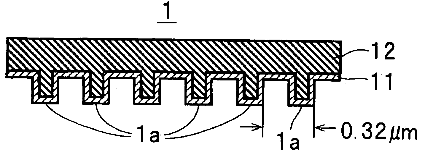
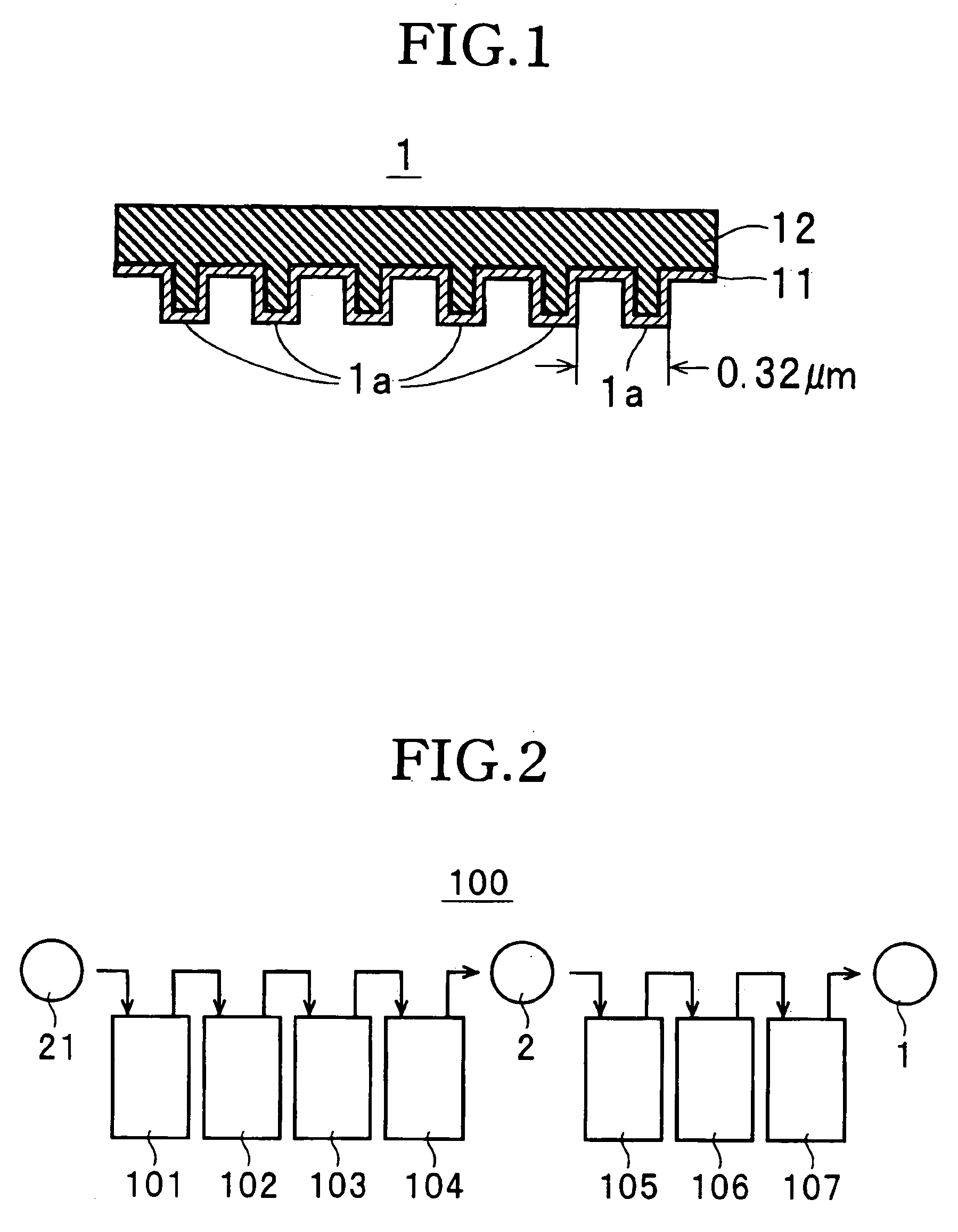
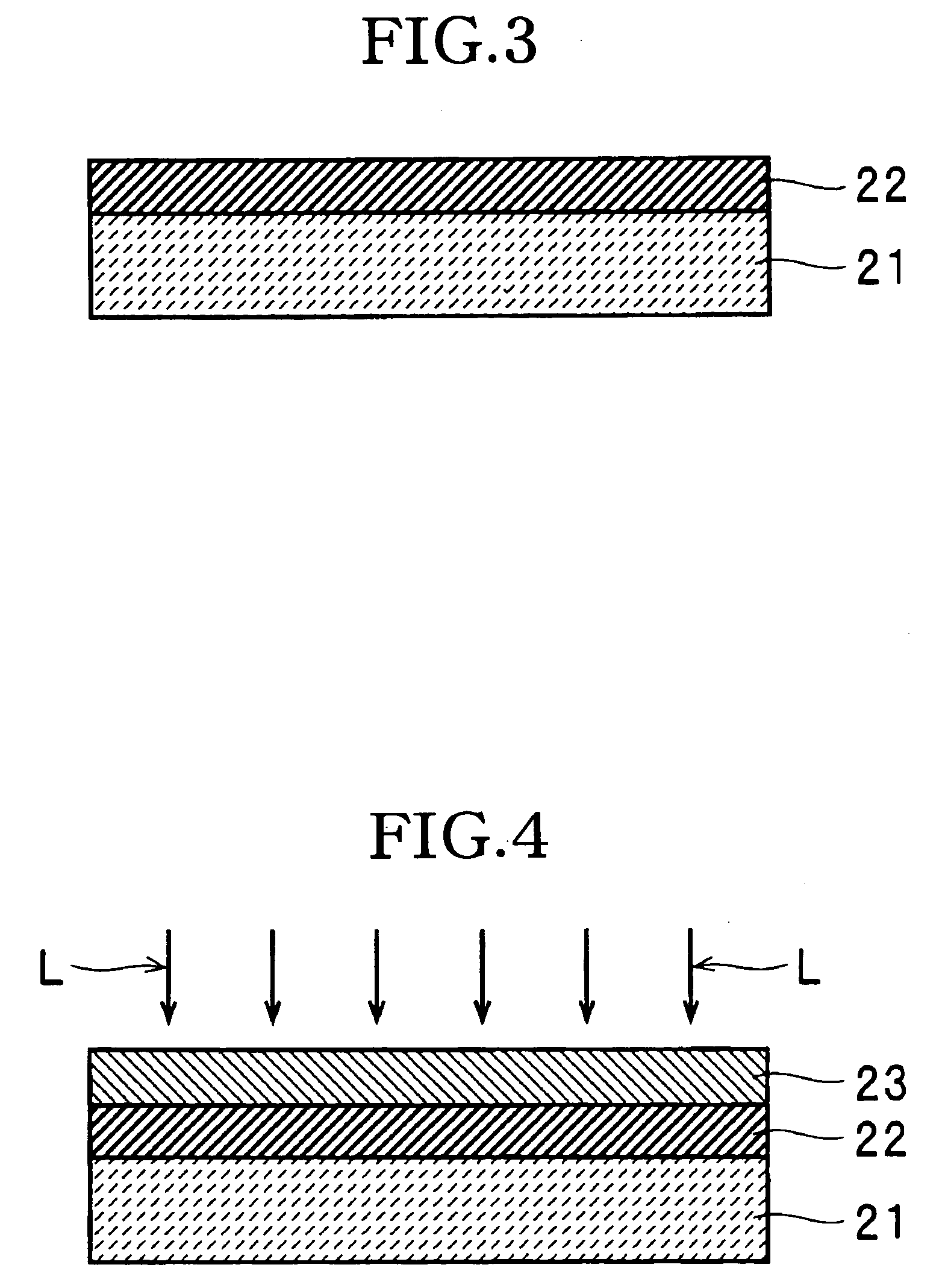
[0089] A photoresist layer 23 having a thickness of 60 nm was formed on a resin layer 22 on a glass board 21 in the above described manner and a laser beam L emitted from the exposing apparatus 103 and having a wavelength λ of 266 nm was projected onto the photoresist layer 23 so that the half-width l of the shortest pit was equal to 138 nm and a pit pattern was formed in the photoresist layer 23, thereby fabricating a sample #1.

[0090] A sample #2 was fabricated in the same manner as the sample #1 except that a pit pattern was formed in the photoresist layer 23 so that the half-width l of the shortest pit length was equal to 149 nm.

[0091] A sample #3 was fabricated in the same manner as the sample #1 except that a pit pattern was formed in the photoresist layer 23 so that the half-width l of the shortest pit length was equal to 160 nm.

[0092] A sample #4 was fabricated in the same manner as the sample #1 except that a pit pattern was formed in the photoresist layer 23 so that the ...


PUM


Abstract

A method for manufacturing a photoresist-coated glass board includes steps of forming a resin layer containing a benzophenone system compound on a glass board, forming a photoresist layer on the resin layer, intermittently projecting a laser beam for exposure having a wavelength λ of 100 nm to 300 nm onto the photoresist layer, forming a latent image of a pit pattern so that a half-width l of a shortest pit length is equal to or shorter than 0.65 λ, and developing the photoresist layer in which the latent image is formed to form a pit pattern in the photoresist layer. According to thus constituted method for manufacturing a photoresist-coated glass board, a photoresist-coated glass board can be formed with pits of a pit pattern in a desired manner using a laser beam having a short wavelength.

Description

BACKGROUND OF THE INVENTION [0001] The present invention relates to a method for manufacturing a photoresist-coated glass board and, particularly, to a method for manufacturing a photoresist-coated glass board which can be formed with pits of a pit pattern in a desired manner using a laser beam having a short wavelength. [0002] Further, the present invention relates to a method for manufacturing a stamper and, particularly, to a method for manufacturing a stamper formed with a pit pattern having a desired height. [0003] Furthermore, the present invention relates to a method for manufacturing a recording medium and, particularly, to a method for manufacturing a recording medium having a substrate formed with a pit pattern having a desired cross section. DESCRIPTION OF THE PRIOR ART [0004] In a process for manufacturing a stamper used for manufacturing an optical recording medium, one known method for forming a minute pit pattern in a photoresist layer on a glass board is the resist p...

Claims


Application Information

Patent Timeline
24 Mar 2005
Publication
US20050064345A1
IPC
G03F7/11; G03F7/00; G11B7/007; G11B7/26
CPC
G03F7/00; G11B7/263; G11B7/261; G11B7/007
Inventors
OYAKE, HISAJI