Marine engine corrosion prevention system

a corrosion prevention and marine engine technology, applied in the direction of machines/engines, liquid handling, packaging goods types, etc., can solve the problems of small engine heat dissipation, corrosive nature of cooling fluid (i.e. water), and marine engine operating in salt-water environment, and achieves relatively simple and short design, effective reduction of corrosion tendency, and easy practice

Inactive Publication Date: 2005-03-31
IBM CORP
View PDF19 Cites 5 Cited by
  • Summary
  • Abstract
  • Description
  • Claims
  • Application Information

AI Technical Summary

Benefits of technology

[0012] The general purpose of the present invention is therefore to provide a corrosion inhibiting apparatus and method which are easy to practice, and which will effectively reduce the tendency of corrosion to accumulate upon the inaccessible surfaces and passageways of an internal combustion engine cooling system. The method has been design to be relatively simple and short, while obviating the difficulties encountered in the practice of prior art processes. To attain this, the present invention contemplates an apparatus for the introduction of an inert gas into the interior cooling system or water jacket of an internal combustion engine, typically somewhere near the highest point of the cooling system. The process is continued by allowing the inert gas to circulate throughout the entire cooling system until all corrosion inducing fluids, such as oxygen and water vapor are expelled through the engine's cooling system intake and exhaust output ports. Finally the inert gas is retained in the system for the length of time it is desired to preserve the cooling system. In addition, an anticorrosive material may be mixed with the inert gas prior to introduction to increase the efficacy of the system. By using an inert gas that is lighter than air, oxygen and water vapor, all of the key elements critical to corrosion are displaced from the system due to the buoyancy of the purging fluid (i.e. inert gas).

Problems solved by technology

Smaller engines typically dissipate heat through the flow of air across the engine.
A common problem with an open loop cooling system is that the cooling fluid (i.e. water) includes all of the contaminants and corrosive components that exist in the fluid.
For example, a marine engine operating in a salt-water environment is subject to the corrosive nature of the salt that accumulates in its cooling system.
The corrosive nature of salt in marine engines can ultimately lead to destruction and / or catastrophic failure of the engine after prolonged exposure to salt.
If not terminated, the corrosion will continue leading to the ultimate destruction of the engine component or a portion thereof.
While this method and apparatus can also be used for marine engines that are still submersed in salt water, the removal of salts from the cooling system is much less effective as salt water is likely to leak into the cooling system during flushing as well as upon completion of the flushing process.
While this common flushing process is generally accepted as the best remedy for the removal of salt water from the engine's cooling system, it is known that the process does not remove all salt from the system.
The flow of fluid through the cooling system is often such that there exist pockets or areas where the fresh water is either not circulated or not circulated in sufficient quantities to remove all of the salt.
As a result, at some point in time the marine engine will be damaged or fail due to corrosion.
Additional drawbacks to the accepted method of flushing include the necessity of removing the boat from the water on a lift or rack, accessibility to a plentiful fresh water source, the necessity of operating the marine engine during the flushing process and the amount of time it takes to complete the flushing process.

Method used


Image

  • Marine engine corrosion prevention system
  • Marine engine corrosion prevention system
  • Marine engine corrosion prevention system

Examples


Embodiment Construction

[0029] Although the disclosure hereof is detailed and exact to enable those skilled in the art to practice the invention, the physical embodiments herein disclosed merely exemplify the invention that may be embodied in other specific structure. While the preferred embodiment has been described, the details may be changed without departing from the invention, which is defined by the claims.

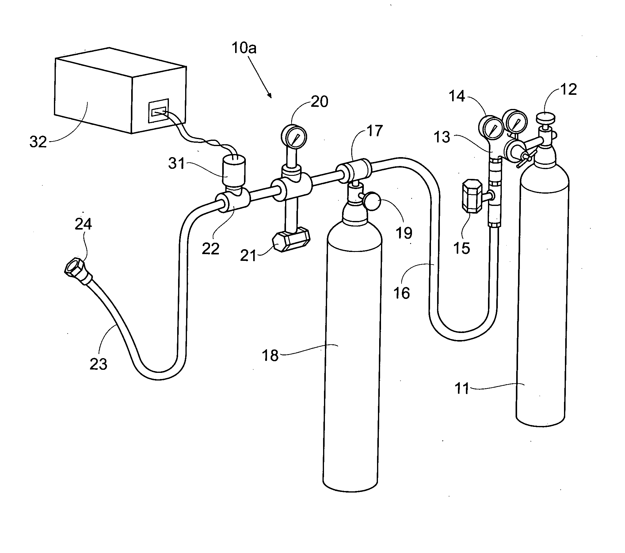
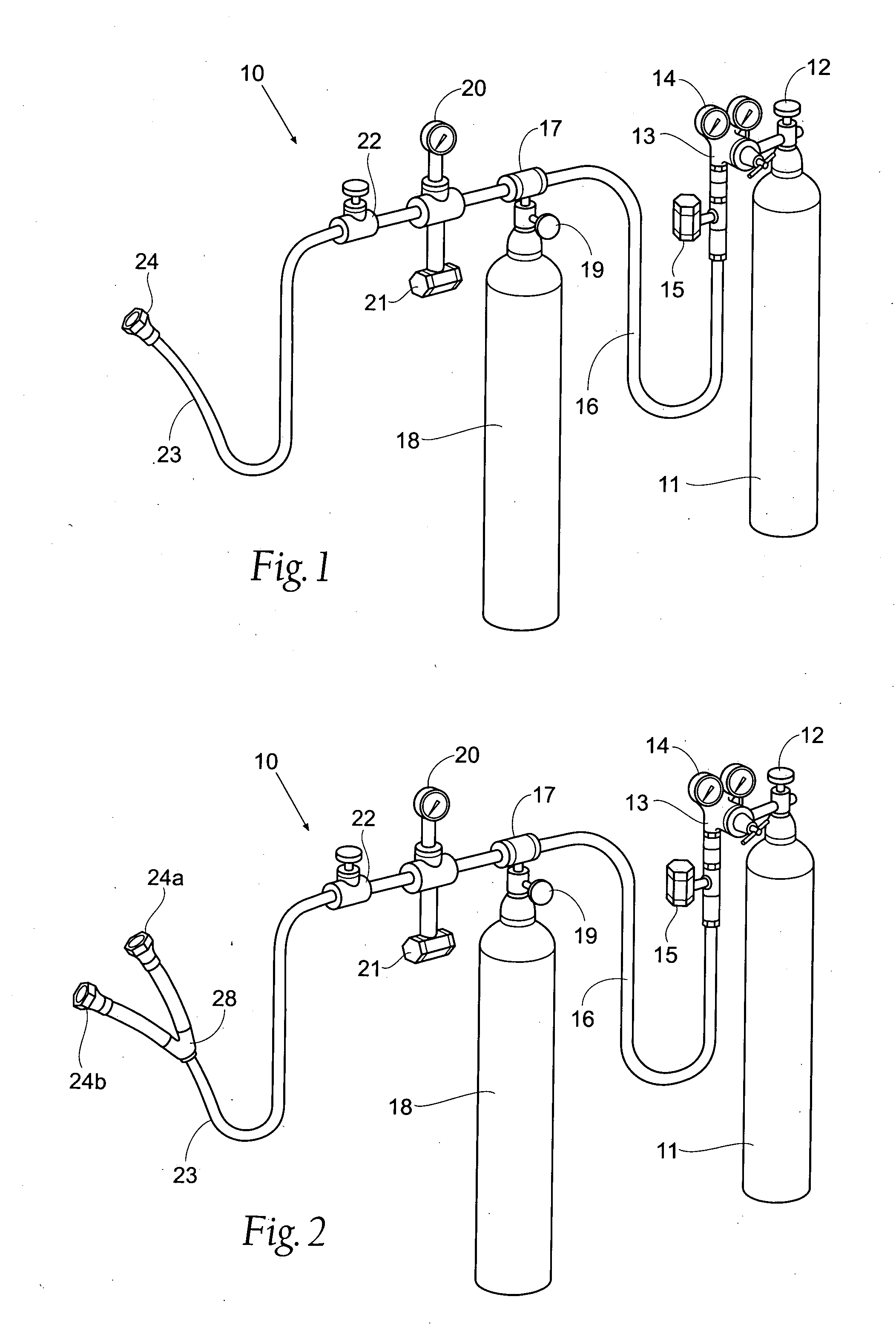
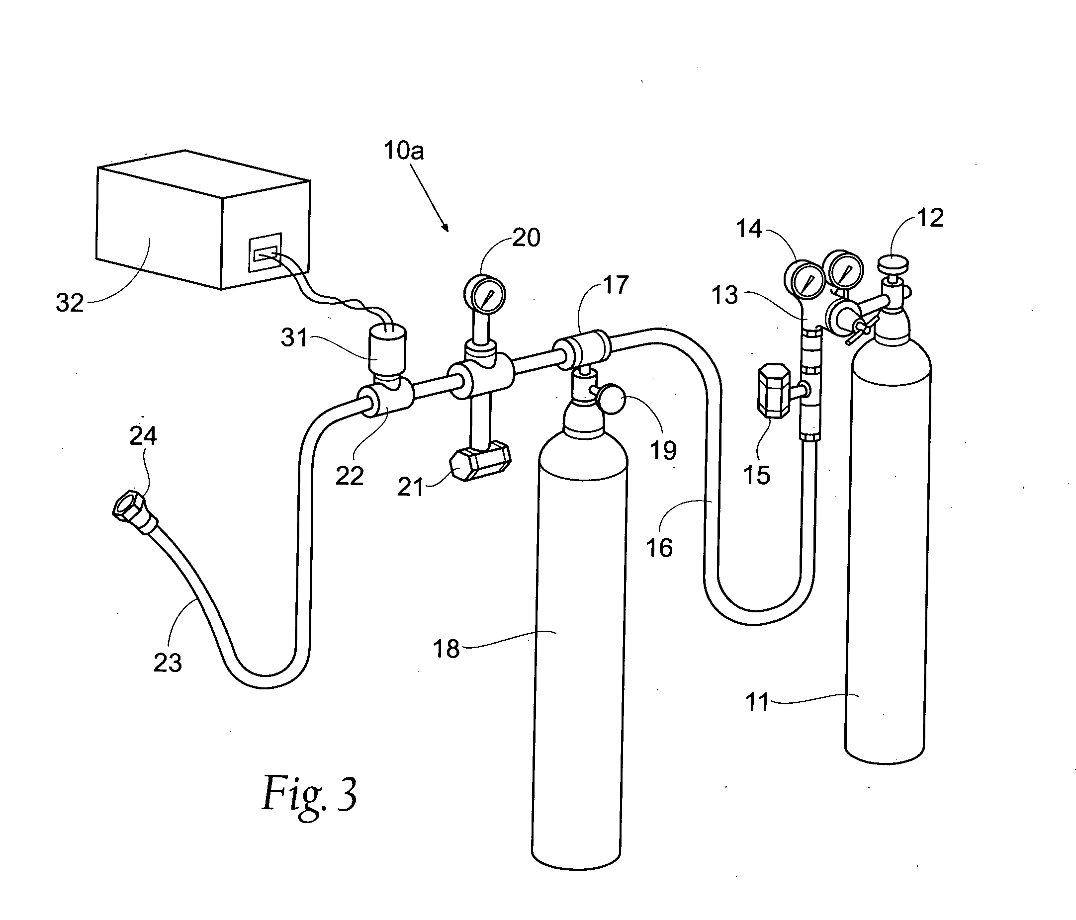
[0030] Referring now to FIG. 1, reference numeral 10 is used to indicate the apparatus of the present invention. The first component includes a cylindrically shaped tank 11 containing a supply of inert gas. Preferred inert gases for the purpose of the present invention include helium and nitrogen. The inert gas is retained within tank 11 under high pressure, and when it is desired to use the apparatus, valve 12 is opened to introduce a supply of gas into the system herein after described. A conventional pressure regulator 13, having the usual pressure gauge 14, is provided in the system 10 adjacen...


PUM

PropertyMeasurementUnit
pressureaaaaaaaaaa
pressureaaaaaaaaaa
corrosionaaaaaaaaaa

Abstract

An apparatus and method for prevention of corrosion with the cooling system of an internal combustion engine is disclosed. The apparatus includes a pressurized inert gas source and a fluid delivery system whereby the gas is dispersed within the cooling system to expel corrosion inducing fluids such as oxygen and water vapor. Methods of use are also disclosed.

Description

BACKGROUND OF THE INVENTION [0001] The present invention relates to an apparatus and method for inhibiting corrosion, and more particularly to a new and improved apparatus and method that prevents the corroding of cooling fluid passageways and other surfaces of internal combustion engines during storage or prolonged periods of non-use. This is accomplished by removing substantially all of the oxygen and / or water vapor from the passageways and surfaces. [0002] Internal combustion engines generate power by controlling multiple, successive explosions of a combustible fuel within one or more combustion chambers. The process generates not only power through the power take off component of the engine, but also heat. The heat generated during the process must be dissipated from the engine to avoid catastrophic failure of the engine or its components. Smaller engines typically dissipate heat through the flow of air across the engine. Air-cooled engines include cooling fins to increase the e...

Claims


Application Information

Patent Timeline
Patent Type & Authority Applications(United States)
IPC IPC(8): F01P3/20F01P11/06
CPCF01P3/205F01P2011/068F01P2011/066F01P11/06
Inventor MCCLURE, THOMAS W.
Owner IBM CORP
Why Eureka
Try Eureka