
Hydraulic torque vectoring differential

a technology of differential and hydraulic torque, applied in the direction of differential gearings, fluid gearings, non-deflectable wheel steering, etc., can solve the problem of very low differential parametric loss, and achieve the effect of being efficient, durable, and fully controllabl

Inactive Publication Date: 2005-03-31
FOLSOM TECH
View PDF4 Cites 38 Cited by
  • Summary
  • Abstract
  • Description
  • Claims
  • Application Information

AI Technical Summary

Benefits of technology

"This patent describes a hydro-mechanical torque vectoring differential that is efficient, durable, and fully controllable. It uses hydraulic units instead of conventional clutches and brakes, which reduces wear and tear and eliminates contamination of the differential oil. The system pressure is maintained at a high level to ensure a fast response time. The technical effects of this invention include improved efficiency, durability, and control of torque distribution between the two wheels."

Problems solved by technology

As the hydraulic units see only differential wheel speed power, the parasitic losses of the differential will be very low when compared to a limited slip or torque-biasing differential that uses conventional clutches and brakes, as the clutches and brakes are slipping or freewheeling when the differential is in normal ‘open’ mode.

Method used


Image

  • Hydraulic torque vectoring differential
  • Hydraulic torque vectoring differential
  • Hydraulic torque vectoring differential

Examples


Embodiment Construction

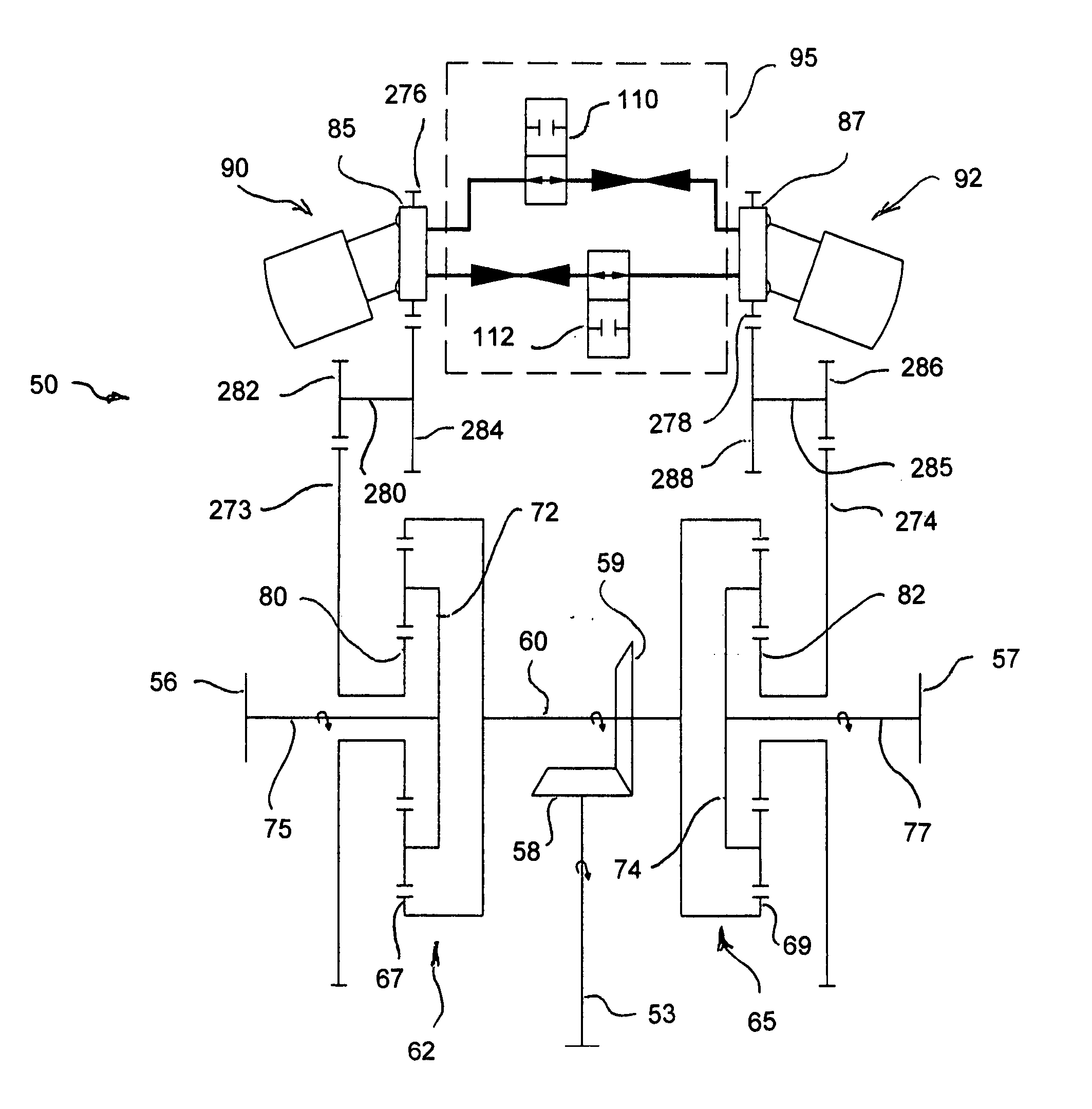
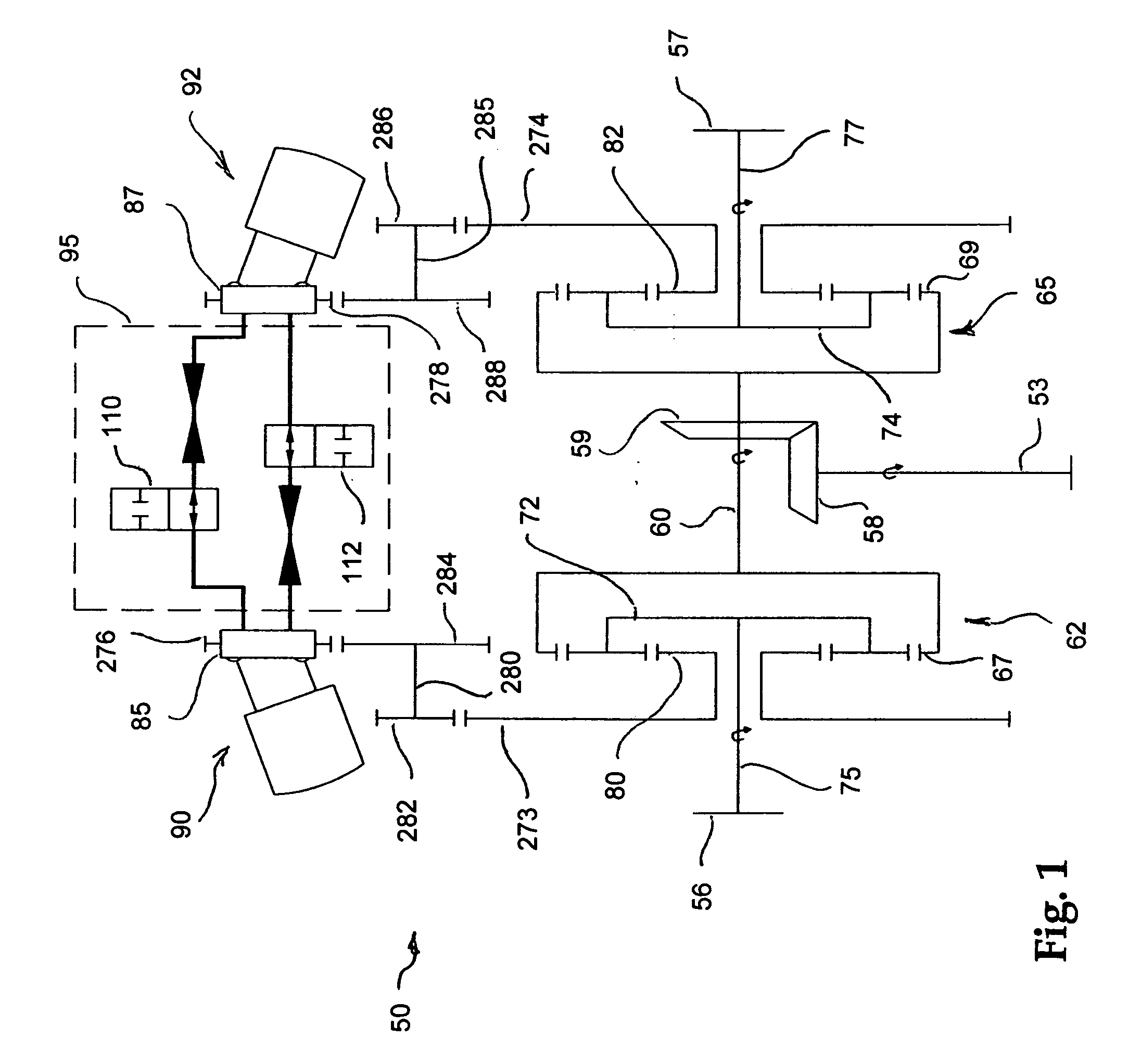
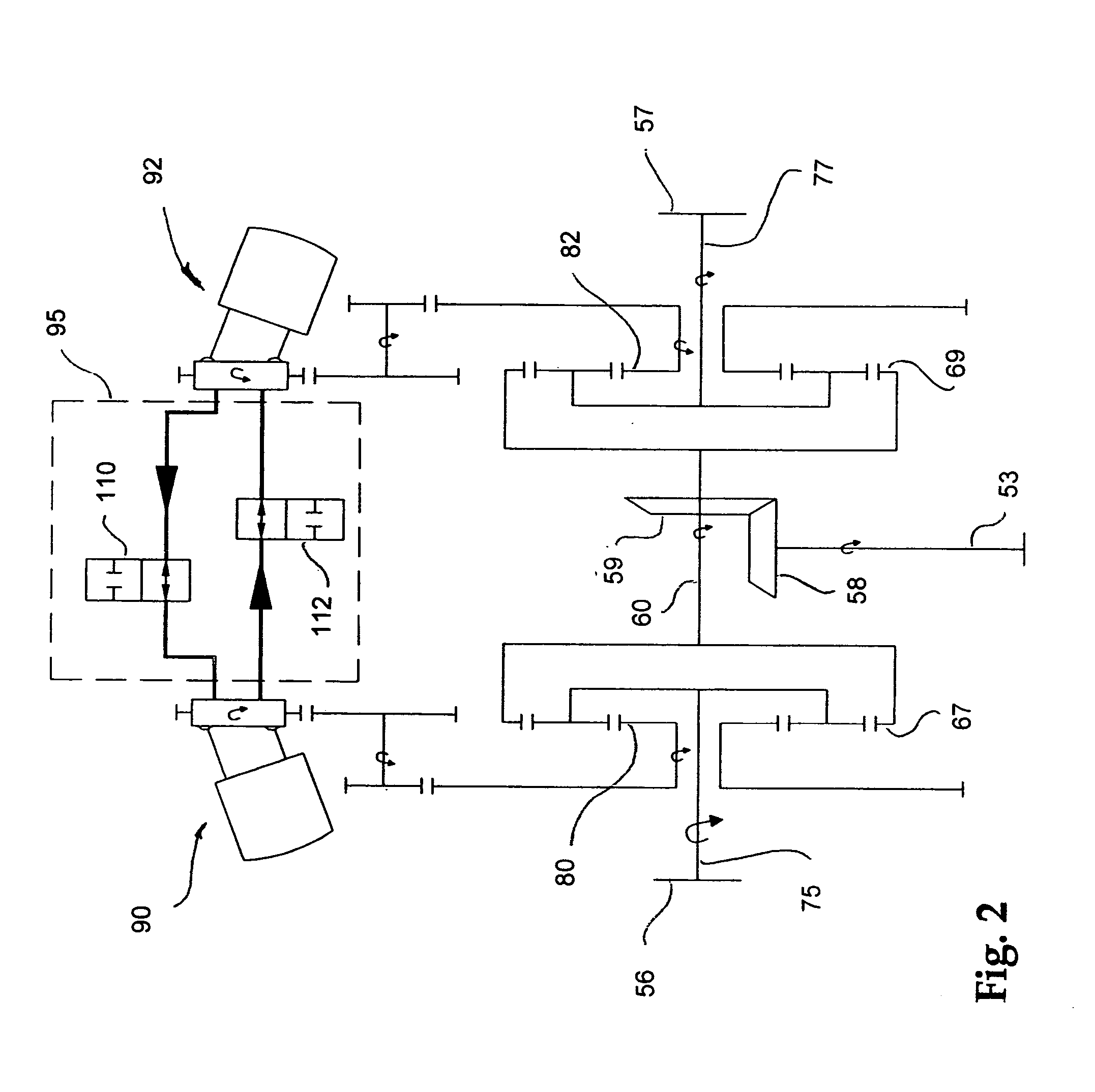
Turning now to the drawings, wherein like reference numerals designated identical or corresponding parts, and more particularly to FIG. 1 thereof, a hydraulic torque vectoring differential 50 is shown schematically, coupling a vehicle drive shaft 53 to right and left wheels 56, 57. An input bevel gear 58 on the input drive shaft 53 drives a driven bevel gear 59 on a transverse shaft 60.

The opposite ends of the transverse shaft 60 are each coupled to and drive a ring gear 67, 69 of right and left epicyclic gear sets 62, 65, respectively. Each epicyclic gear set 62, 65 has a planet carrier 72, 74, respectively, coupled to a respective right or left hand wheel axle 75, 77, respectively, and each epicyclic gear set 62, 65 has a sun gear 80, 82 meshing with a torque plate 85, 87 of respective right and left rotating bent-axis hydrostatic units 90, 92 hydraulically coupled together through a center manifold 95 and mechanically coupled through the epicyclic gear sets 62, 65 and the tran...


PUM


Abstract

A hydraulic torque vectoring differential includes two epicyclic gear sets and two variable displacement hydrostatic units. Each hydrostatic unit is coupled to a reaction member of one of each of the epicyclic gear sets, each of which also has a first gear element coupled to an input drive shaft for power input from a prime mover of said vehicle and a third gear element coupled to an output shaft operatively driving the wheels of the vehicle. The hydrostatic units are hydraulically coupled so that hydraulic fluid pressurized in one hydrostatic unit drives the other hydrostatic unit, and fluid pressurized in the other hydrostatic unit drives the one hydrostatic unit. A control system controls the displacement of the variable displacement hydrostatic units. Power from the prime mover flows primarily through the epicyclic gear sets to the output shafts, and only differential power is passed through the hydrostatic units, thereby isolating the hydraulic units from the primary power flow and making use of low displacement hydrostatic units possible for said differential power flow through said differential. The desired torque distribution between the two wheels is determined by existing conventional computer controls based on inputs from known traction sensors.

Description

This invention relates to differentials in vehicle drive trains, and more particularly to a hydraulic torque vectoring differential capable of vectoring torque from the vehicle transmission at any desired ratio to any drive wheel. BACKGROUND OF THE INVENTION A torque biasing differential powers both drive wheels in conditions where one wheel could slip and lose traction. An ordinary open differential, standard on most vehicles, can lose traction by spinning one wheel during acceleration or cornering because the open differential shifts power to the wheel with less grip. A torque biasing differential system, however, is designed to sense which wheel has the better grip, and biases the power to that wheel, while maintaining some lesser power to the other wheel. During straight forward acceleration, torque biasing differential can produce close to ideal 50 / 50 power split to both drive wheels, resulting in improved traction over a conventional open differential. In cornering, while ac...

Claims


Application Information

Patent Timeline
Patent Type & Authority Applications(United States)
IPC IPC(8): B60K17/04B60K17/10B62D11/06F04B1/20F16HF16H37/08F16H47/04F16H48/06F16H48/30
CPCB60K17/046B60K17/105F04B1/2014F16H47/04F16H2048/364F16H48/26F16H48/30F16H48/36F16H2039/005F16H48/10
Inventor FOLSOM, LAWRENCE R.TUCKER, CLIYE
Owner FOLSOM TECH
Learn More