
Fluid-assisted medical devices, systems and methods

a technology of medical devices and fluids, applied in the field of fluid-assisted medical devices, systems and methods, electrosurgical, can solve the problems of tissue desiccation, tissue sticking to electrodes, tissue perforation,

Active Publication Date: 2005-03-31
MEDTRONIC ADVANCED ENERGY
View PDF7 Cites 257 Cited by
  • Summary
  • Abstract
  • Description
  • Claims
  • Application Information

AI Technical Summary

Problems solved by technology

Current dry tip electrosurgical devices can cause the temperature of tissue being treated to rise significantly higher than 100° C., resulting in tissue desiccation, tissue sticking to the electrodes, tissue perforation, char formation and smoke generation.
Undesirable results of such transmission to adjacent tissue include unintended thermal damage to the tissue.
However, an uncontrolled or abundant flow rate of saline can provide too much cooling at the electrode / tissue interface.
This, in turn, can result in longer treatment time to achieve the desired tissue temperature for treatment of the tissue.
Long treatment times are undesirable for surgeons since it is in the best interest of the patient, physician and hospital to perform surgical procedures as quickly as possible.
RF energy delivered to tissue can be unpredictable and often not optimal when using general-purpose generators.
However, once these settings are chosen, the actual power delivered to tissue and associated heat generated can vary dramatically over time as tissue impedance changes over the course of RF treatment.
Current dry tip electrosurgical devices are not configured to address a change in power provided by the generator as tissue impedance changes or the associated effect on tissue and rely on the surgeon's expertise to overcome this limitation.
One drawback of non-contact thermal methods is the “heat sink effect” where flowing arterial blood leads to dissipation of the thermal energy.
In any event, laser units are expensive, bulky and generally not portable.
They are also difficult to use as an en face view of the bleeding ulcer is often required.
For these reasons, laser photocoagulation has generally fallen out of favor for the treatment of ulcer bleeding.
This method is generally effective for mucosal bleeding but may not be effective in coagulating an eroded artery in a bleeding ulcer.
Compression of the blood vessel also reduces the blood flow and reduces the heat sink effect.
These methods are effective in hemostasis but carry a potential risk of inducing bleeding when an adherent probe is pulled off a bleeding vessel.
Thus, cost and non-portability issues associated with laser therapy have generally made it a less favorable treatment for ulcer hemostasis.
Injection therapy generally has an advantage over the above contact thermal devices in that the injection does not need to be very accurate and can be performed through a pool of blood, but the cost of the medication is a disadvantage.
While there were no significant differences between most clinical outcomes of APC versus GP patients, investigators observed that APC was significantly slower than GP and more difficult to use because of several features of APC: it could not coagulate through blood or water, smoke was common which interfered with visualization and increased gut motility, tamponade of bleeders was not possible, and tangential coagulation was difficult or often blind.
Although APC is a “no touch technique,” the catheter was difficult to hold 2-3 mm off the mucosa, which affords the best coagulation of a dry field.
These features resulted in 6 failures and crossovers with APC and none with GP.
The authors concluded that for hemostasis of bleeding angiomas, both the APC and GP were effective, but there were substantial problems with the newer APC device, and overall the GP performed better.

Method used


Image

  • Fluid-assisted medical devices, systems and methods
  • Fluid-assisted medical devices, systems and methods
  • Fluid-assisted medical devices, systems and methods

Examples


Embodiment Construction

Throughout the present description, like reference numerals and letters indicate corresponding structure throughout the several views, and such corresponding structure need not be separately discussed. Furthermore, any particular feature(s) of a particular exemplary embodiment may be equally applied to any other exemplary embodiment(s) of this specification as suitable. In other words, features between the various exemplary embodiments described herein are interchangeable as suitable, and not exclusive.

The invention provides systems, devices and methods that preferably improve control of tissue temperature at a tissue treatment site during a medical procedure. The invention is particularly useful during surgical procedures upon tissues of the body, where it is desirable to shrink tissue, coagulate fluids (e.g. oozing blood), and at least partially occlude lumens, vessels (e.g. lumen of blood vessels (e.g. arteries, veins), intestines (e.g. absorbent vessels)) and airways (e.g. tr...


PUM


Abstract

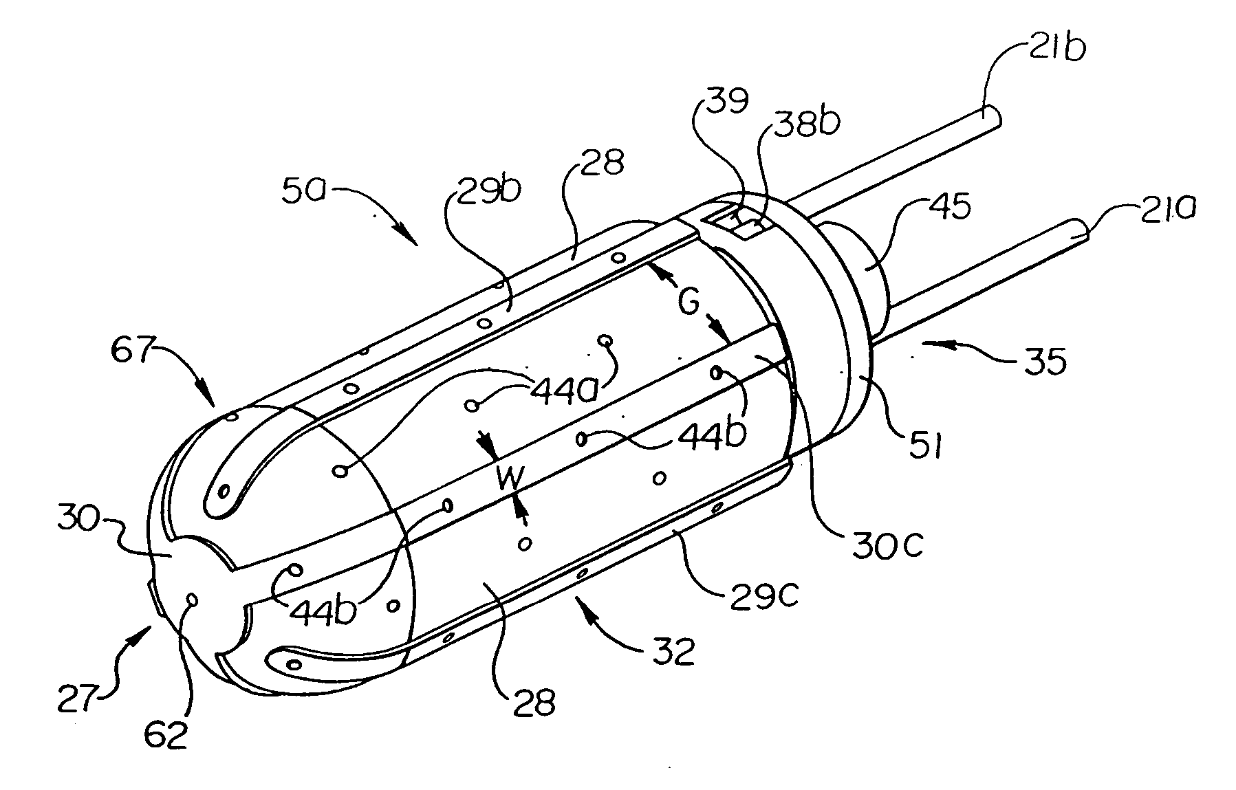
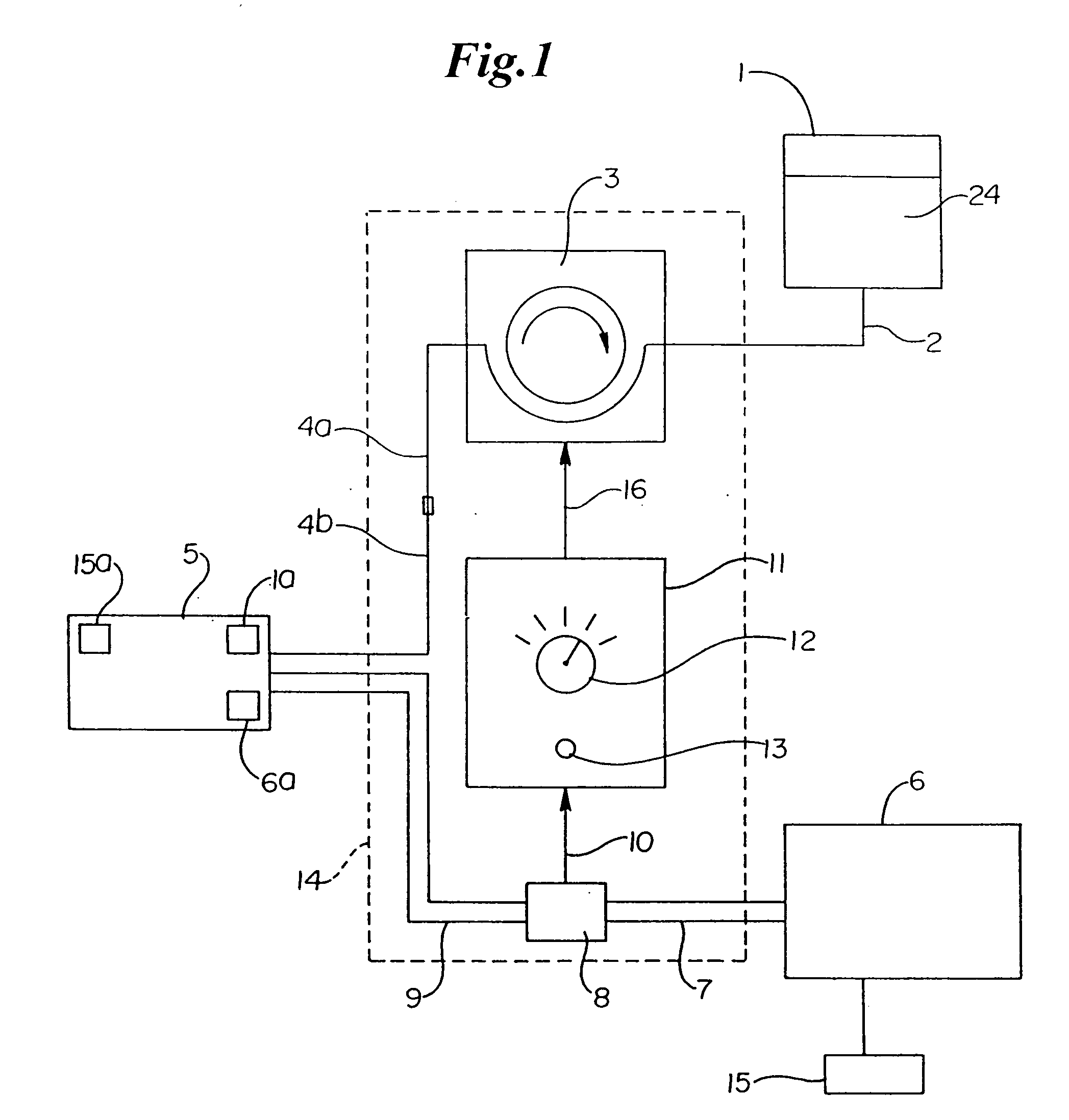
A medical device (5) is provided which comprises a catheter tube having a distal end and a lumen, and configured to assist in applying tamponage to a bleeding source in a gastrointestinal tract when flexed. A catheter tip having a catheter tip outer surface is assembled with the tube adjacent the distal end of the tube. The catheter tip comprises a probe body comprising an electrically insulative material, at least one electrode pair located on the probe body which comprises a first electrode spaced from a second electrode, and a fluid distribution manifold to direct a fluid from inside the probe body towards the tip outer surface. The manifold comprises a central passage within the probe body and a plurality of lateral passages which extend from the central passage towards the tip outer surface. An extendable injection needle is housed within the central passage to provide treatment to tissue.

Description

This application is being filed as a PCT International Patent application in the name of TissueLink Medical, Inc. (a U.S. national corporation), applicant for the designation of all countries except the US, and Michael E. McClurken (a U.S. resident and citizen), applicant for the designation of the US only, on 11 Dec. 2002. FIELD OF THE INVENTION This invention relates generally to the field of medical devices, methods and systems for use upon a body during surgery. More particularly, the invention relates to electrosurgical devices, methods and systems for use upon tissues of a human body during therapeutic endoscopy. BACKGROUND Electrosurgical devices configured for use with a dry tip use electrical energy, most commonly radio frequency (RF) energy, to cut tissue or to cauterize blood vessels. During use, a voltage gradient is created at the tip of the device, thereby inducing current flow and related heat generation in the tissue. With sufficiently high levels of electrical en...

Claims


Application Information

Patent Timeline
IPC IPC(8): A61B18/14
CPCA61B10/02A61B18/1492A61B2018/00011A61B2018/00494A61B2218/002A61B2018/1425A61B2018/1435A61B2018/1497A61B2018/00809
Inventor MCCLURKEN, MICHAEL E.
Owner MEDTRONIC ADVANCED ENERGY
Learn More