Electron microscope

a technology of electron microscope and microscope, which is applied in the direction of instruments, material analysis using wave/particle radiation, nuclear engineering, etc., can solve the problems of low image contrast of enlarged specimen images, difficulty in discriminating astigmatism correction directions, and low image contrast of images, so as to improve the operation capability of electron microscope and high reproducibility

Active Publication Date: 2005-04-07
HITACHI HIGH-TECH CORP
View PDF3 Cites 19 Cited by
  • Summary
  • Abstract
  • Description
  • Claims
  • Application Information

AI Technical Summary

Benefits of technology

According to the present invention, by automating the astigmatism correction, conventionally carried out manually, in combination with the focus correction, the operator can be allowed for obtaining an ima...

Problems solved by technology

But, in case the astigmatism correction is tried under a greatly defocused condition, the enlarged specimen image has a low image contrast and the astigmatism correction direction becomes very difficult to discriminate.
On the other hand, when the focus correction is performed under a condition that a large astigmatic aberration exists, the image contrast of an image is lowered similarly and determination of an exact focus position is difficult to achieve.
In other words, when only the focus correction is completed and the astigmatism remains, the enlarged specimen image becomes blurred, giving rise to degradation of image quality and inaccuracy of analytical position.
In operator-based adjustment, the operator must adjust three of focus, X-direction astigmatism and Y-direction astigmatism at a time while deciding the contrast of image and for an operator having poor experience...

Method used


Image

  • Electron microscope
  • Electron microscope
  • Electron microscope

Examples


first embodiment

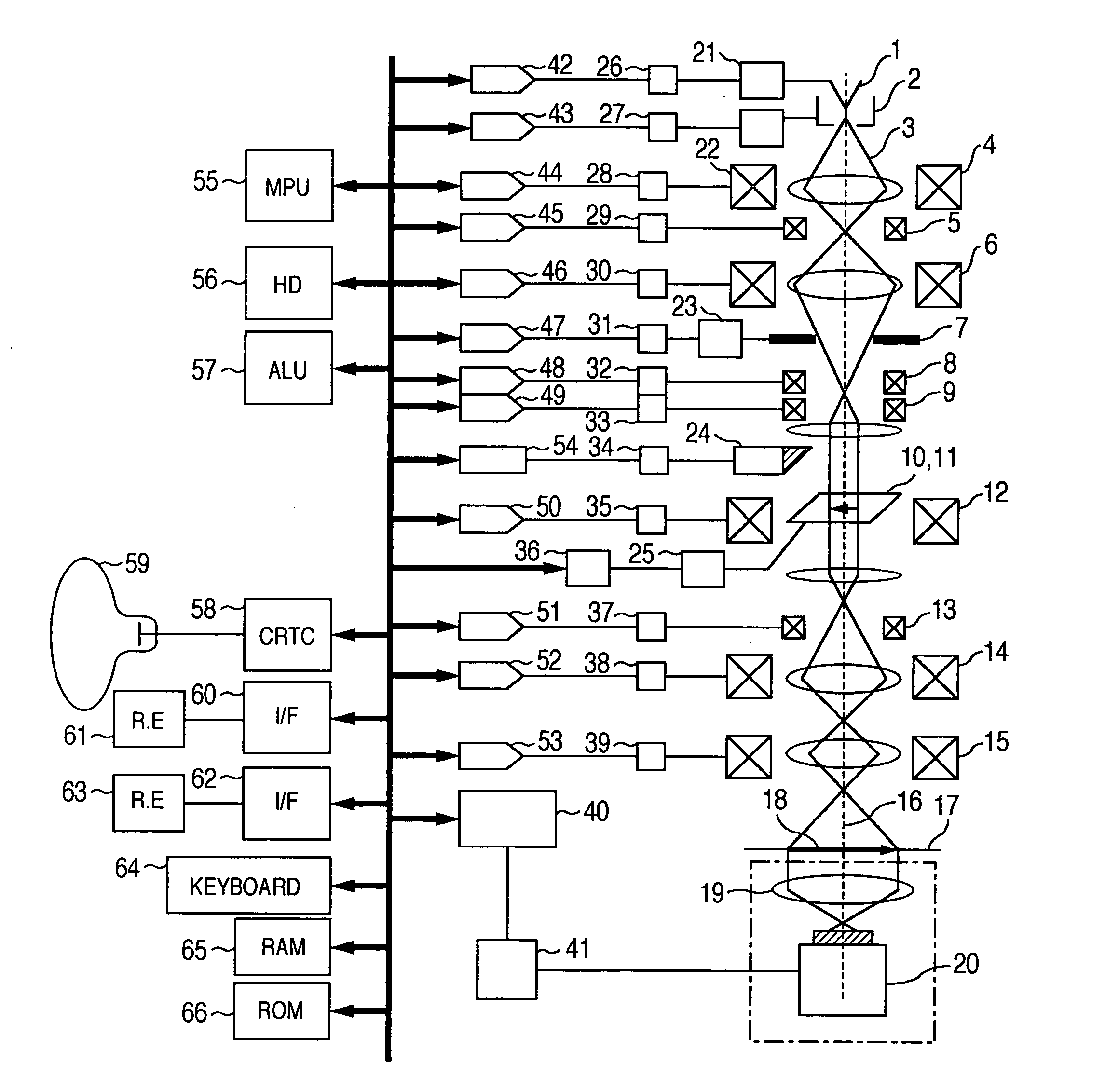
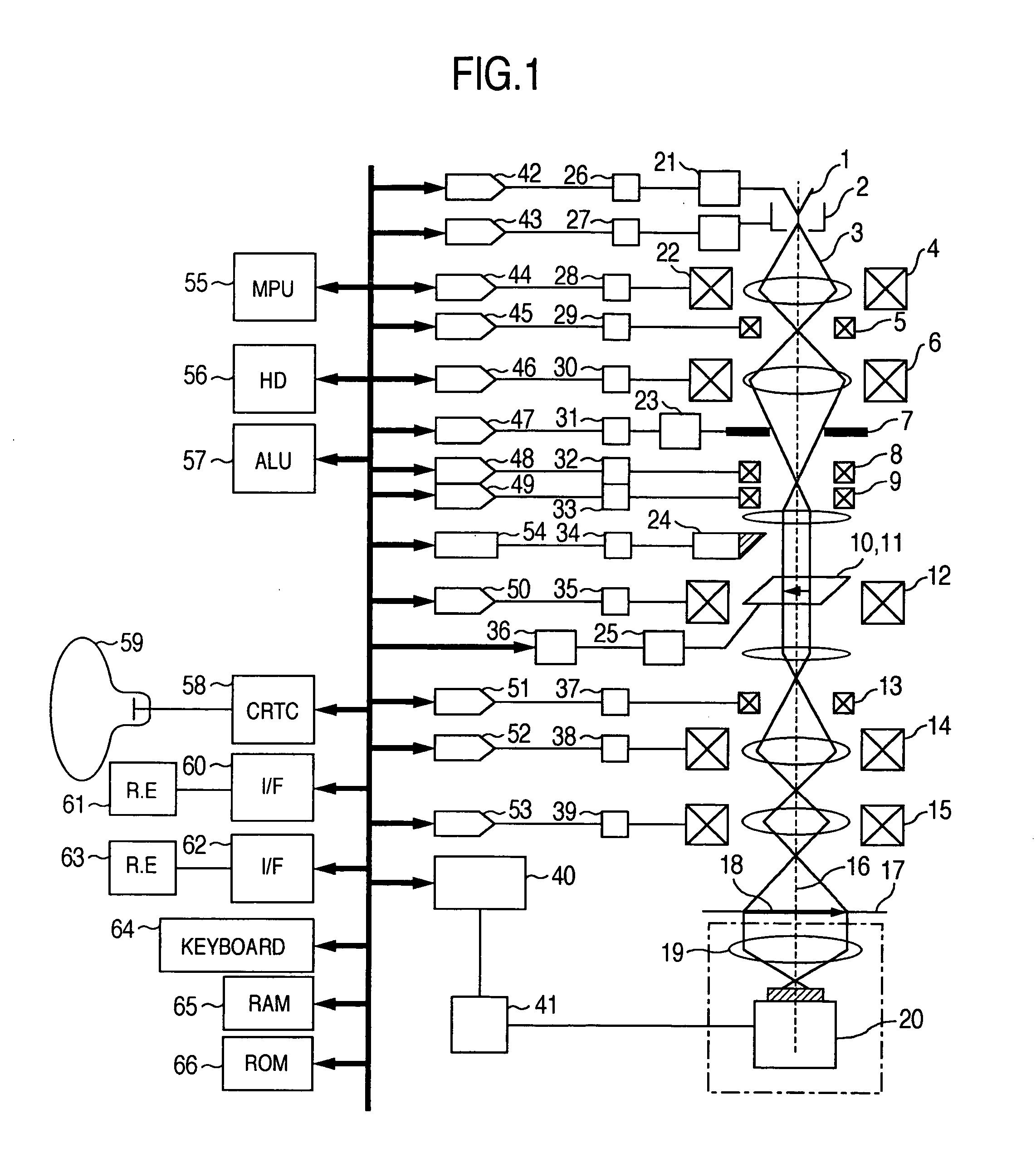
By making reference to a flowchart in FIG. 6, the present invention will be described. In the present embodiment, the electron microscope shown in FIG. 1 is used to decide whether the focus of an enlarged specimen image is defocused and at the same time whether astigmatism exists and to perform automatic correction, thereby solving the first problem.

In step S101, the use of the electron microscope is started. A desired specimen 11 is mounted to the specimen stage 10 and is then inserted to the electron microscope. In step 102, a desired magnification is set by means of the magnification switching rotary encoder 61 shown in FIG. 1. Concurrently, data of electron beam source precedently recorded in the ROM 66 is called out and processed by the microprocessor 55 so that a current may be delivered out of a DAC 42 and a stabilizer 26. This current is supplied to the emitter 1 via a cathode power supply 21 and electrons are emitted from the emitter 1. As for acceleration voltage, data is...

second embodiment

Referring now to a flowchart in FIG. 11, this invention will be described. The present embodiment makes a decision as to whether the focus of an enlarged specimen image is defocused and as to whether an astigmatic aberration exists so as to perform automatic correction, thereby solving the first problem. The flowchart in FIG. 11 shows algorithm capable of determining an image sharpness coefficient dependent on angular directions with a view to simplifying algorithm and speeding up operation.

In step 201, the use of the electron microscope is started. A desired specimen 11 is mounted to the specimen stage 10 and is then inserted to the electron microscope. In step S202, setting of observation magnification, respective lens coil currents, respective deflection coil currents, focus correction parameters and astigmatism correction parameters is carried out. Step S202 corresponds to the step S102 explained in connection with FIG. 7.

In step S203, the focus is changed. This step correspo...

fifth embodiment

Referring now to a flowchart in FIG. 15, this invention will be described. In the present embodiment, correction is made by taking hysteresis of the objective lens coil and hysteresis of an image integration filter during image pick up into consideration, thereby solving the third problem. Here, an example of focus correction will be taken but the same process can also be used in stigmator coil current adjustment.

The hysteresis will be explained with reference to FIG. 14. A graph in FIG. 14 shows the relation between coil current value and image sharpness coefficient, where abscissa represents objective lens coil current values or stigmator coil current values and ordinate represents image sharpness coefficients.

It is now assumed that the change direction of current is defined as shown by arrow. Further, assumptively, the image sharpness coefficient at each point is calculated by using an enlarged specimen image rendered to have hysteresis of past images in time series by means o...


PUM


Abstract

In an electron microscope, focus correction is carried out automatically, an astigmatic difference amount is displayed and astigmatism correction is executed quantitatively. Enlarged specimen images obtained by irradiating an electron beam on a specimen while changing excitation currents of an objective lens and of a stigmator coil are picked up by a capturing unit comprised of an optical lens and a capturing device and image sharpness coefficients are calculated by means of an arithmetic logic unit. A suitable astigmatism correction direction is chosen on the basis of an angular component value of the obtained image sharpness coefficients and then, a correction excitation current is supplied to a stigmator coil to correct astigmatism and a correction excitation current is supplied to an objective lens coil to perform focus correction.

Description

BACKGROUND OF THE INVENTION The present invention relates to electron microscopes and more particularly, to an electron microscope capable of automatically adjusting the focus of an electron lens and astigmatism of an electron beam. Conventionally, in observing, measuring, analyzing and searching a field of view of an enlarged specimen image with an electron microscope, an operator participates in performing focusing and astigmatism adjustment while directly watching the enlarged specimen image. In adjusting focus and astigmatism, while the focus correction is carried out in the direction of height of a specimen (referred to as Z direction), the astigmatism correction is carried out in respect of astigmatic aberrations in 0° and 90° directions (X direction) of the specimen and in respect of astigmatic aberrations in 45° and 135° directions (Y direction) of the specimen and therefore adjustments in three directions in total must be accomplished. Namely, when only the focus correcti...

Claims


Application Information

Patent Timeline
IPC IPC(8): H01J37/22G01N23/04H01J37/153H01J37/21H01J37/26H01J37/28
CPCG01N23/04H01J2237/216H01J2237/1532H01J37/26
Inventor INADA, HIROMI
Owner HITACHI HIGH-TECH CORP
Why Eureka
Try Eureka