Bipolar machine

a bipolar machine and joule heating technology, applied in the direction of dynamo-electric components, acyclic motors, cooling/ventilation arrangements, etc., can solve the problems of joule heating due to circulatory current, eddy current effect, unrecognized, etc., and homopolar machines may be only about 70% or less efficien

Inactive Publication Date: 2005-04-07
WILSDORF DORIS
View PDF15 Cites 22 Cited by
  • Summary
  • Abstract
  • Description
  • Claims
  • Application Information

AI Technical Summary

Problems solved by technology

In fact, the dissipation of energy through joule heating on account of circulatory currents, i.e. the eddy current effect, has so far remained unrecognized for the case of homopolar machines, even though it is well known for electric machine parts without deliberate current, in particular iron cores of electromagnets, transformers, in which eddy currents are supp

Method used


Image

  • Bipolar machine
  • Bipolar machine
  • Bipolar machine

Examples


Embodiment Construction

A. Regarding Current Channeling Means (FIGS. 1 to 6)

Referring now to the drawings, wherein like reference numerals designate identical or corresponding parts throughout the several views, the present invention will now be described.

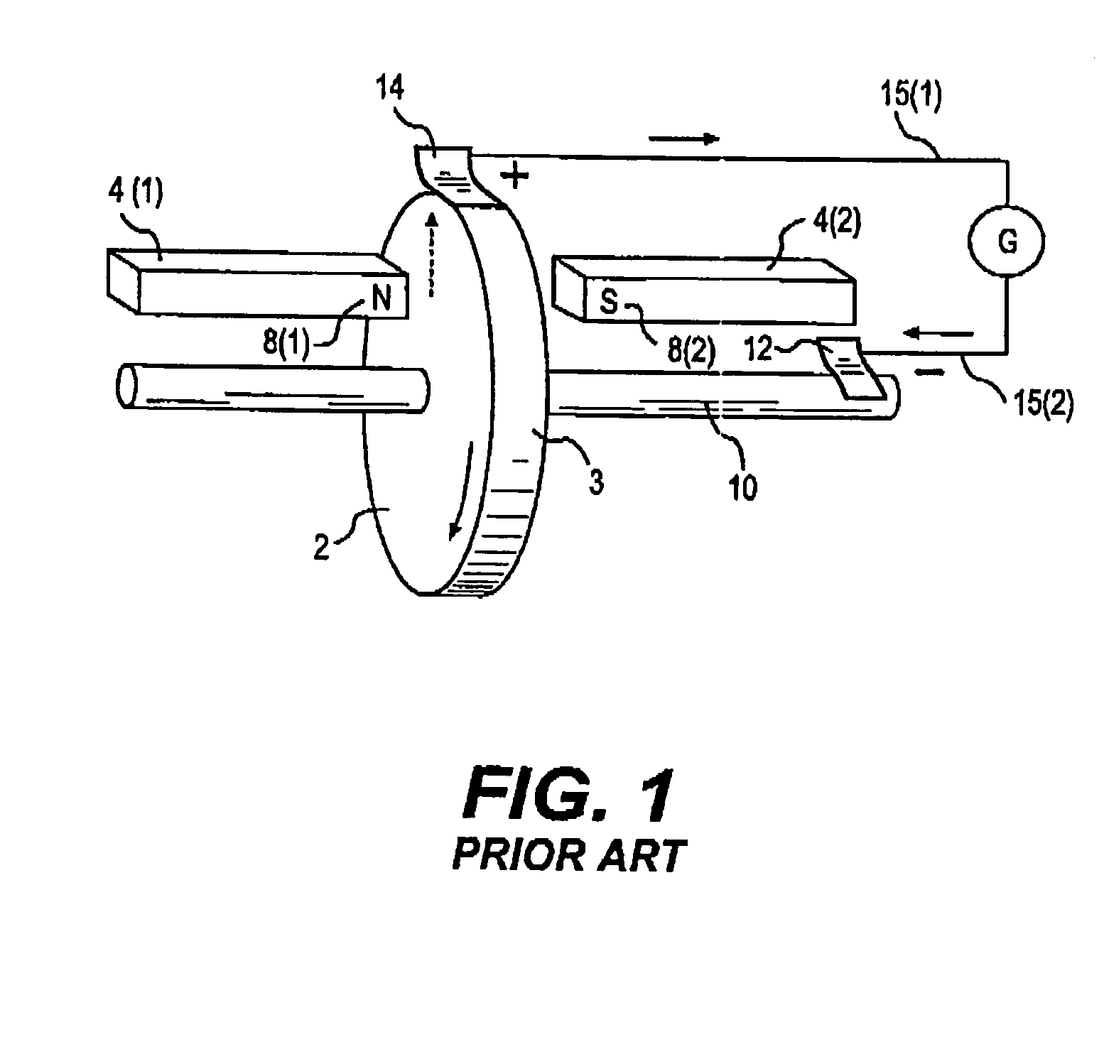
FIG. 1 (prior art) is a reproduction of FIGS. 2-38of ref [1]. It is a perspective view that shows the basic structure of type I homopolar machines as invented 1831 by Michael Faraday. Herein FIG. 1 depicts the type I homopolar machine as a generator, but it can be also used as a motor. It includes an electrically conductive rotor 2 between magnetic poles 8(1) and 8(2) of two bar magnets 4(1) and 4(2) and is mechanically rotated in counter-clockwise direction by means of electrically conductive axle 10, to which rotor 2 is electrically connected. As a result of the motion of rotor 2 an EMF is induced in the area of rotor 2 that is penetrated by the magnetic flux, B, of magnets 4(1) and 4(2). By magnitude and direction that EMF is proportional to [v×B] wh...


PUM


Abstract

A novel homopolar machine with at least one electrically conductive rotatable rotor having at least one predetermined current path, a plurality of current channel insulation layers, and a magnetic field source configured to apply a magnetic field penetrating the rotor and intersecting the current channels when the rotor rotates. The current channel insulation layers are configured for anisotropic current flow both to inhibit eddy currents and to channel current flow between predetermined correlated brush pairs. Two particular configurations are proposed, wherein the source of magnetization generates in the rotor two separate zones with magnetic flux in opposite directions, while the current channel insulation layers guide the current consecutively through these so as to generate the same rotation-sense of Lorentz force.

Description

BACKGROUND OF THE INVENTION 1. Field of the Invention The present invention relates to a “bipolar machine,” a class of homopolar motor / generator, or in general homopolar machine, with increased voltage per current turn, the capability of operating with direct and alternating or three-phase current, and other advantages. 2. Background Three basic types of homopolar motors are depicted (PRIOR ART) in FIG. 1 (type I), FIG. 2 (type II), FIG. 3 (type III), and a practical example of a type III machine previously reported to have been constructed but without evidence that it ever operated (FIGS. 4 and 5). In the past, the practical use of homopolar motors and generators has been inhibited by the large resistance of conventional graphite-based electrical brushes. In principle, multi-contact metal brushes, including metal fiber brushes, foil brushes, and hybrid brushes, i.e. comprising resilient multi-contact metal material that will establish a multitude of electrical contact spots wh...

Claims


Application Information

Patent Timeline
IPC IPC(8): H01R39/24H02K9/28H02K31/02
CPCH01R39/24H02K13/003H02K31/02H02K9/28
Inventor WILSDORF, DORIS
Owner WILSDORF DORIS
Why Eureka
Try Eureka