
Range resistors for AC-DC transfer measurements

Inactive Publication Date: 2005-04-07
WALCOTT HENRY O
View PDF2 Cites 12 Cited by
  • Summary
  • Abstract
  • Description
  • Claims
  • Application Information

AI Technical Summary

Benefits of technology

[0018] It is a primary object of the invention is to provide a highly accurate range resistor that is particularly useful for higher attenuation ratios, at “Volt×Hz” products up to 100,000,000, in voltage ranges from 100 to 1000 volts with increased accuracy over known art at AC frequencies as high as 1 MHz.
[0021] Yet another object of the invention is to provide a precision attenuator of improved accuracy and stability through a reduction of the temperature rise of the resistive element due to internal heating during operation and thus accomplish a reduction in the time and extent of warm-up drift and drift resulting from level changes, as well as a reduction in measurement errors due to changes in voltage coefficient and frequency response due to changes in resistor temperature. SUMMARY OF THE INVENTION
[0023] The particular geometry of these shield portions and a specially selected location of the resistor body inside the shield structure, essentially eliminate errors in the signal transfer function due to the effect of stray capacitance from the external grounded shield to the resistor body, where the capacitance, is distributed in a gradient along the length of the resistor body. The high AC voltage under test is also distributed along the length of the resistor in a gradient.

Problems solved by technology

The effect of the capacitive current is to divert a portion of the input current from the output by bypassing it to the shield, causing AC to DC difference error that increases with frequency.

Method used


Image

  • Range resistors for AC-DC transfer measurements
  • Range resistors for AC-DC transfer measurements
  • Range resistors for AC-DC transfer measurements

Examples


Embodiment Construction

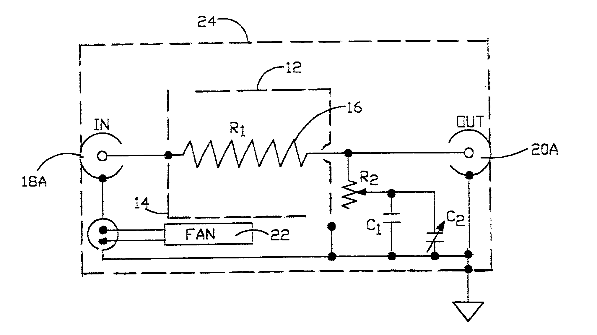
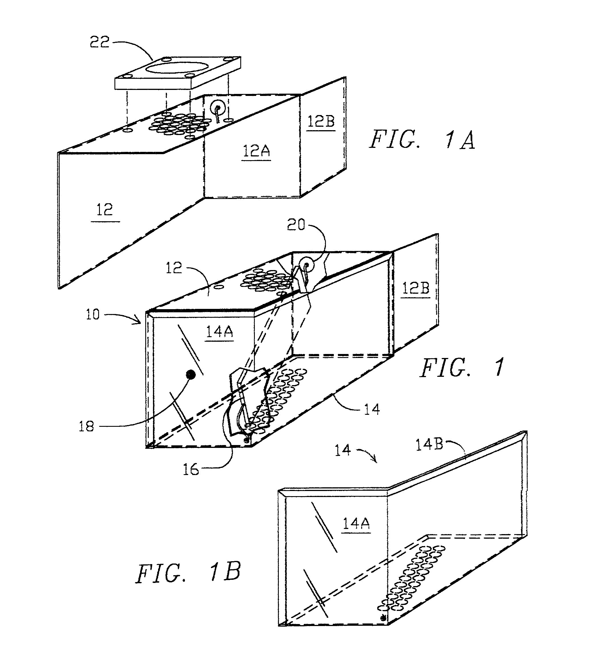
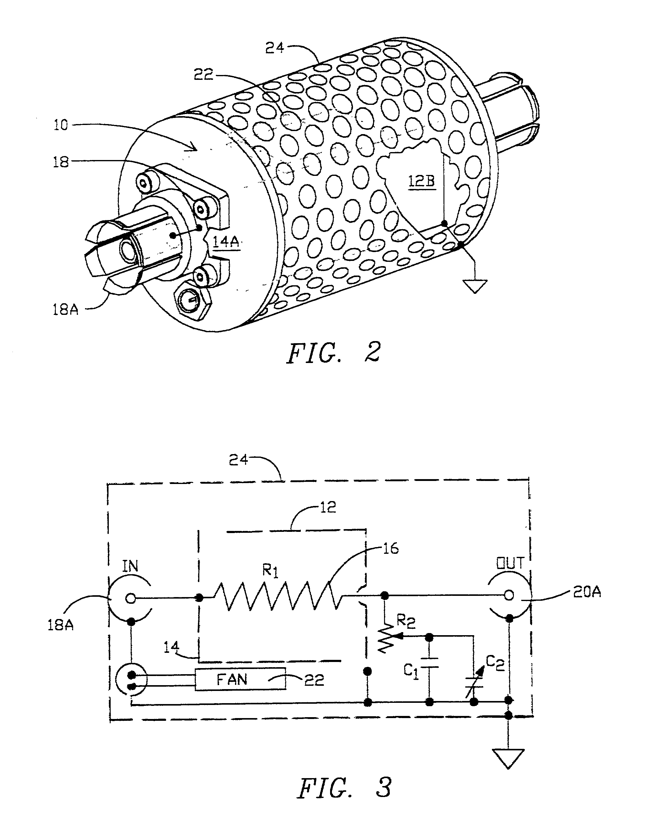
[0031]FIG. 1 is a perspective view of the primary shield assembly 10 of a high frequency compensated range resistor of the present invention, consisting of a rectangular metal enclosure composed of two mating half portions: a grounded portion 12 and an ungrounded portion 14, the two half portions being insulated from each other by electrical insulation, bonded at their junctions.

[0032] Resistor 16, seen in part through a cutaway opening and otherwise shown in hidden lines, is a generally rectangular high quality non-inductive resistor with end leads, and is located in an inclined diagonal orientation in both horizontal and vertical axes as shown, extending between diagonally opposite corners of the shield assembly.

[0033] Grounded shield portion 12 includes the top panel, far side panel and far end panel, which has an extension flap 12B extending to the rear.

[0034] The ungrounded shield portion 14 includes the near side panel, bottom panel and near end panel 14A which is connected...


PUM


Abstract

A range resistor, for deployment with a low voltage AC measuring instrument as a voltage range multiplying attenuator, provides increased accuracy in the measurement of high AC voltages at frequencies up to 1 MHz, particularly when large attenuation ratios are needed. Passive guarding and neutralizing structure permits the use of higher value resistors for a given frequency response accuracy and an intrinsically lower input capacitance than is obtainable with conventional structure. Very low drift and voltage coefficients are achieved by a coordinated thermal design. Applications include high accuracy voltage measurement in the 10 to 1000 volt range with low input signal current when attenuation is resistively scaled to match the operating input level of the measuring device to be used, typically a thermocouple and / or digital or analog precision voltmeter.

Description

PRIORITY [0001] Benefit is claimed under 35 U.S.C. § 119(e) of pending provisional application Ser. No. 60 / 262,242 filed Jan. 17, 2001.FIELD OF THE INVENTION [0002] The present invention relates to the field of electrical voltage measurements and instrumentation, and more particularly it is directed to improvements in range resistor modules for high accuracy measurement of high AC voltages at high frequencies in conjunction with low voltage measuring instruments, including analog and digital instruments and particularly thermal converters and thermal transfer standard instruments. The invention discloses novel structure in range resistor modules that accomplishes enhanced high frequency compensation by neutralizing stray capacitance to ground distributed along the length of the resistor. BACKGROUND OF THE INVENTION [0003] Thermoelectric elements first came into use for AC voltage and current measurements in the late 1920's and were first used for AC-DC transfer measurements in the 1...

Claims


Application Information

Patent Timeline
IPC IPC(8): G01R1/20G01R19/22
CPCG01R19/22G01R1/203
Inventor WALCOTT, HENRY O.
Owner WALCOTT HENRY O
Learn More