Diamond cooled laser gain assembly

a laser gain and diamond technology, applied in lasers, laser cooling arrangements, laser details, etc., can solve the problems of diode-pumped output power, solid-state lasers ultimately limited by thermal and mechanical properties of gain medium, further restrictions on the performance of systems, degradation of output beam quality, etc., to achieve simplified dielectric coatings, good thermal conductivity, and small temperature rise in laser gain medium

Inactive Publication Date: 2005-04-07
SPECTRA PHYSICS
View PDF10 Cites 12 Cited by
  • Summary
  • Abstract
  • Description
  • Claims
  • Application Information

AI Technical Summary

Benefits of technology

[0013] Another object of the present invention is to provide high power solid-state lasers, and their methods of use, that have a small temperature rise in the laser gain medium. Yet another object of the present invention is to provide high power solid-state lasers, and their methods of use, that have simplified dielectric coatings with good thermal conductivity.
[0014] A further object of the present invention is to provide high power solid-state lasers, and their methods of use, that have reduced thermally induced stress.

Problems solved by technology

The output power available from diode-pumped, solid-state lasers is ultimately limited by the thermal and mechanical properties of the gain medium.
However, often the method used to mount and cool the gain medium places further restrictions on the performance of the system.
Even before the material fails mechanically, thermo-optical effects can lead to a degradation of the output beam quality and a loss in output power, which results from the formation of a thermally induced lens in the gain medium.
The disadvantage of this scheme is that the temperature in the laser medium is often higher than if it were cooled transversely.
High temperatures can lead to many undesirable effects such as stress buildup and even fracture of the gain material, or of the bonds to other materials; in addition to a reduction in efficiency of the laser due to other effects, such as a decrease of the upper-state lifetime of the laser transition.
A disadvantage of this embodiment is the complexity of the thin-film coating that has to be applied to the disk.
There are two problems: first, the coating needs to be highly reflective at one wavelength and highly transmissive at the other.
Secondly, the coating on the back of the disk is in direct contact with the liquid coolant, which imposes additional restrictions on its design and durability.
However, there are several disadvantages with these embodiments.
In addition, the inevitable differences in thermal expansion of the materials used in the disk, the interface layers, and the solid cooling element can cause stresses to built up in the structure and even cause the bond to fail altogether, or the material to fracture.
There is also an increase in the detrimental lensing effects due to the more severe bulging of the material.
Although the original active mirror designs allowed for stress-free radial expansion, as taught by Abate, et al., these embodiments remove this advantage.
This is particularly problematic for materials such as Nd:YVO4 that have an anisotropic thermal expansion, and which are not suited to the method taught by Sutter and Kafka in US Patent Application “Expansion Matched Thin Disk Laser and Method for Cooling” Attorney Docket Number 18120-012, incorporated herein by reference.
Yet a further disadvantage of these embodiments is that the surface where most of the heating occurred was farthest away from the cooling element.

Method used


Image

  • Diamond cooled laser gain assembly
  • Diamond cooled laser gain assembly
  • Diamond cooled laser gain assembly

Examples


Embodiment Construction

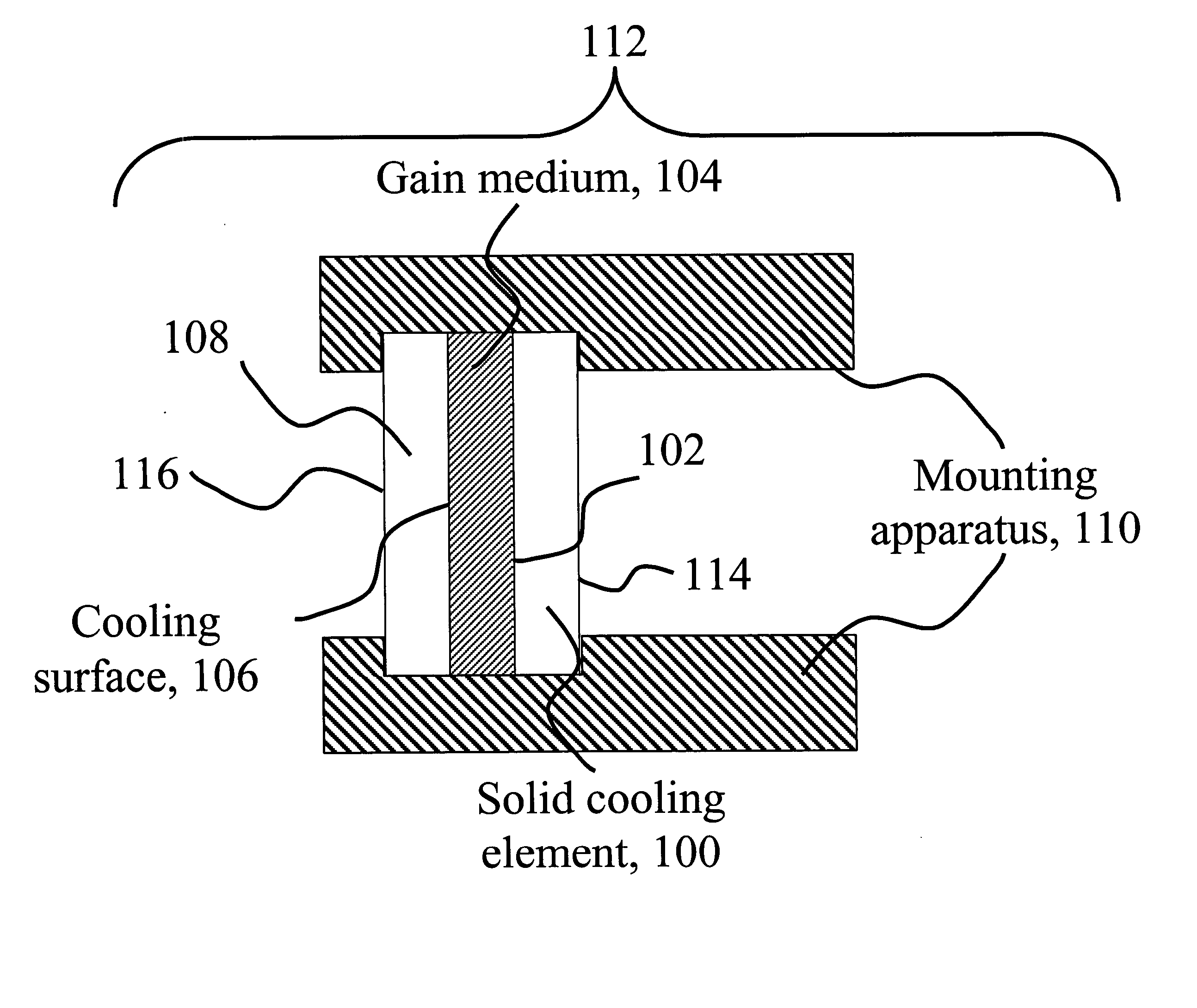
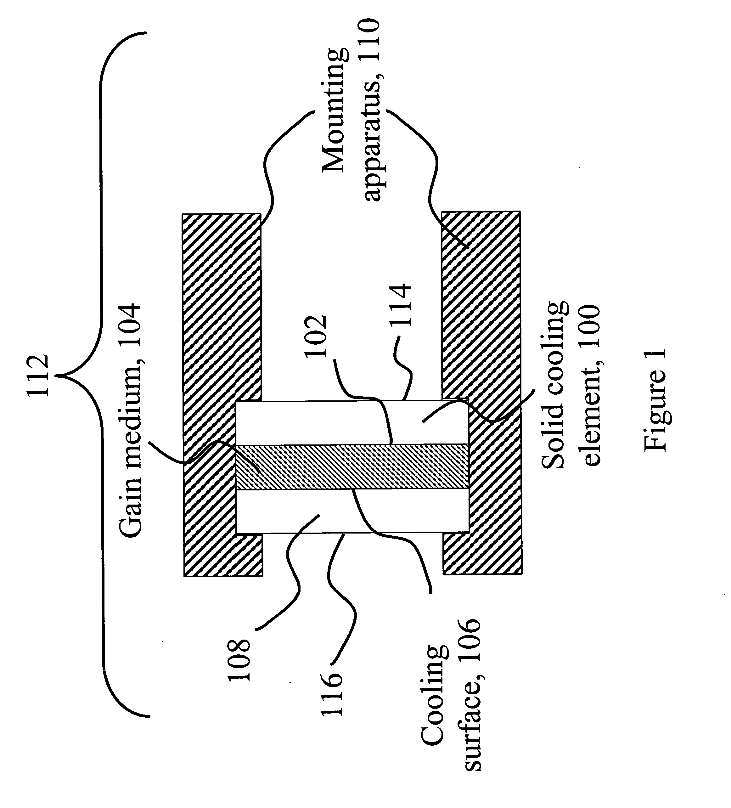
[0024] As illustrated in FIG. 1, in one embodiment of the present invention, a gain assembly 112 comprises: at least a first solid cooling element 100 that is in physical contact with, but not bonded to, a cooling surface 102 of gain medium 104. Two cooling surfaces 102 and 106, and two solid cooling elements 100 and 108 are provided. Heat flow through the gain medium 104 can be substantially one-dimensional, in a direction substantially normal to the cooling surfaces 102 and 106. Solid cooling elements 100 and 108 are held in contact with gain medium 104 by mounting apparatus 110, by applying opposing forces to solid cooling elements 100 and 108 in a direction substantially normal to the cooling surfaces 102 and 106. In various embodiments, one or both of solid cooling elements 100 and 108 can be, sapphire, CVD diamond, single-crystal CVD diamond, a material having a thermal conductivity >100 Wm−1K−1, and the like. At least one of the solid cooling elements 100 and 108 can have a h...


PUM


Abstract

An optical system includes a laser oscillator or a laser amplifier. The optical system includes a gain medium that is optically coupled to a pump source. A solid cooling element is in physical contact with, but not bonded to, a cooling surface of the gain medium. A mounting apparatus holds the solid cooling element to the gain medium. In a preferred embodiment the gain medium is a thin disk gain medium and the solid cooling-element is made from CVD-diamond.

Description

BACKGROUND OF THE INVENTION [0001] 1. Field of the Invention [0002] This invention relates to a laser gain medium and more particularly to a laser gain assembly using diamond to achieve improved cooling, reduced thermally induced lensing, and improved thermo-mechanical robustness. [0003] 2. Description of Related Art [0004] The output power available from diode-pumped, solid-state lasers is ultimately limited by the thermal and mechanical properties of the gain medium. However, often the method used to mount and cool the gain medium places further restrictions on the performance of the system. Even before the material fails mechanically, thermo-optical effects can lead to a degradation of the output beam quality and a loss in output power, which results from the formation of a thermally induced lens in the gain medium. This lens is a combination of the effects caused by the temperature dependence of the refractive index, often referred to as a “bulk thermal lens,” and from the defor...

Claims


Application Information

Patent Timeline
Patent Type & Authority Applications(United States)
IPC IPC(8): H01S3/04H01S3/042
CPCH01S3/042H01S3/0405
Inventor SPENCE, DAVID E.PETERSEN, ALAN B.KAFKA, JAMES D.
Owner SPECTRA PHYSICS
Why Eureka
Try Eureka