Method of coating an SLA part

a technology of sla parts and ear shells, applied in the field of stereolithography methods, can solve the problems of inconsistency in the removal rate of materials, poor customer satisfaction, and discoloration of the appearance and achieve the effects of less susceptible to build-up, high gloss exterior finish, and fast build-up times of the ear shell

Inactive Publication Date: 2005-04-07
INTECH INDS
View PDF15 Cites 2 Cited by
  • Summary
  • Abstract
  • Description
  • Claims
  • Application Information

AI Technical Summary

Benefits of technology

[0013] An object and advantage of the present invention is that it permits the use of a lower resolution stereo-lithography mode to create the ear shell, thereby permitting faster build times for the ear shell.
[0014] Another principle object and advantage of the present invention is that the high gloss exterior finish is less susceptible to the build up of cerumen (ear wax), dirt, and perspiration on the ear shell.
[0015] Another principle object and advantage of the present invention is that the high gloss finish is produced without buffing or polishing the ear shell, thus saving labor.
[0016] Another principle object and advantage of the present invention is that avoiding buffing and polishing avoids removing material from the ear shell, thus preventing poor customer satisfaction due to poor fit, discomfort, poor retention, and acoustic feedback due to loose or inadequate aperture sealing with the inner ear.
[0017] Another principle object and advantage of the present invention is that the high gloss finish is produced without air abrading or vibratory polishing methods.
[0018] Another principle object and advantage of the present invention is that it can be performed by less skilled operators than are needed for other methods, such as buffing, polishing, air abrading, and vibratory polishing.

Problems solved by technology

However, hearing instrument manufactures have experienced that matte finishes tend to more readily display build up of cerumen (ear wax), dirt and perspiration that can often discolor the appearance of the ear shell.
Conventional buffing and polishing methods create inconsistencies in the rate of material removal and vary by operator skills and experience.
This leads to poor customer satisfaction as a result of poor fitting, comfort, retention and acoustic feedback due to loose or inadequate aperture sealing within the inner ear.
Air abrading and or vibratory polishing methods are also less accurate at producing a smooth surface without losing the accuracy benefits of stereo-lithography ear shells.

Method used


Image

  • Method of coating an SLA part
  • Method of coating an SLA part

Examples


experiment 1

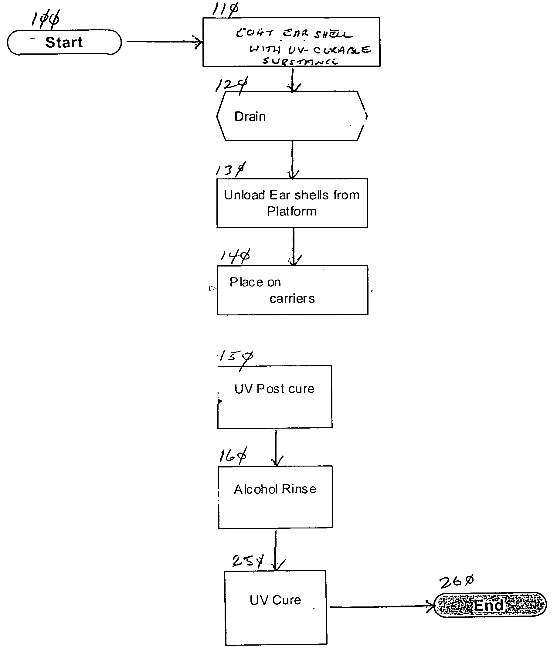
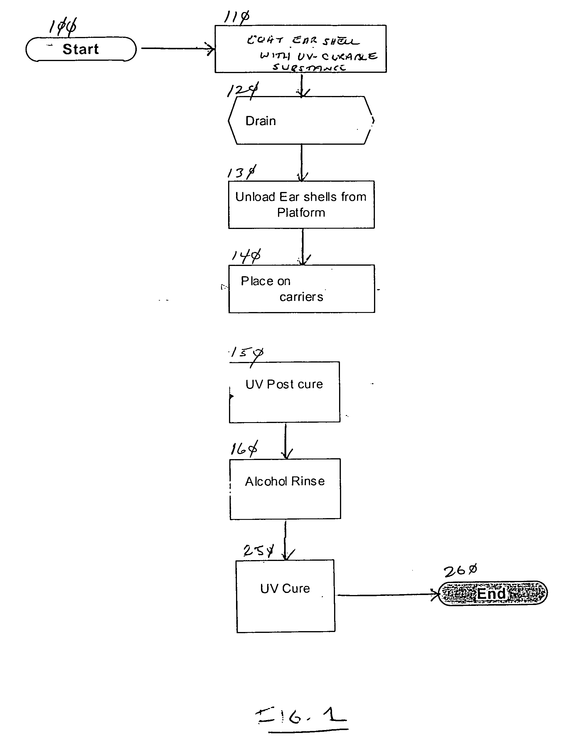
[0030] Hearing aid ear shells manufactured through stereo-lithography were placed on the platform of the SLA apparatus and submerged in the SLA resin. The platform was then raised, allowing the SLA resin to drain off the ear shells. The shells were allowed to drain for 5 to 10 minutes. Forceps were then used to grip the supports of the ear shells, and the ear shells were placed on a carrier and exposed to UV light for about 3 minutes. The ear shells were then placed in an ultrasound alcohol bath for about 2 minutes. The ear shells were then removed from the alcohol bath. Finally, the ear shells were cured in UV light for an additional 30 minutes.

[0031] The resulting ear shells had a smooth, high gloss exterior finish. If a microscopic examination were to be made of the ear shell, the exterior would appear seamless, since the same SLA resin was used to coat the ear shells as was used to manufacture them.


PUM

PropertyMeasurementUnit
glossaaaaaaaaaa
thicknessaaaaaaaaaa
ultrasoundaaaaaaaaaa

Abstract

A method for producing a high gloss exterior finish on a hearing aid ear shell. The method consists of the steps of: coating the ear shell with a UV-curable substance and/or a stereo-lithography resin; draining the UV-curable substance off the ear shell; exposing the ear shell to UV light to cure the UV-curable substance; removing any excess of the UV-curable substance; and exposing the UV-curable substance to UV light a second time.

Description

BACKGROUND OF THE INVENTION [0001] Stereo-lithography methods are presently being used to manufacture highly accurate hearing instrument ear shells over prior conventional pouring or UV methods. SLA methodology has two predominant resolution modes derived by how fine the stl file is sliced for processing. High resolution mode consists of building the part to be manufactured in either 0.002″ / 0.05 mm or 0.004″ / 0.10 mm layered thicknesses. [0002] The layering process has a faceting or stair stepped effect on the completed ear shells exterior surfaces. The finer the slice thickness the less noticeable the effect is. Further more, this high resolution mode has proportionately longer build times as a result of twice the amount of layers processed. The present invention smoothens the faceted surfaces of the ear shell, allowing lower resolution mode, i.e. faster build times to be used while generating a high gloss finish. [0003] Stereo-lithographic ear shells manufactured without additional...

Claims


Application Information

Patent Timeline
Patent Type & Authority Applications(United States)
IPC IPC(8): B05D3/02B05D3/06B05D7/02
CPCB05D3/0209B29C67/0066B05D7/02B05D3/067B29C64/135
Inventor STEVENS, RANDAL A.INSIXIENGMAY, SID C.
Owner INTECH INDS
Why Eureka
Try Eureka