Sheet glass forming apparatus

a glass forming and sheet technology, applied in the field of sheet glass forming apparatus, can solve the problems of limited range of production rate, and practical limitations of the angle of tilt, and achieve the effect of faster and more uniform glass flow

Inactive Publication Date: 2005-04-14
CORNING INC
View PDF26 Cites 27 Cited by
  • Summary
  • Abstract
  • Description
  • Claims
  • Application Information

AI Technical Summary

Benefits of technology

The present invention includes design features that can be used alone or in combination to facilitate faster, more uniform flow of glass through the apparatus and allows the thickness of the sheet to be adjusted.
An overflow device is provided at the far end of the trough and is used in conjunction with tilting of the apparatus to expand the range of glass flow rate and glass viscosity for which this invention will produce satisfactory product. The overflow device may be used in conjunction with tilting of the apparatus, changes in glass flow rate, and changes in glass viscosity (temperature) to regulate the thickness profile of the sheet. In addition, the forming apparatus can be made with non-linear weirs to provide a greater range of flow rates.
The glass flow in the inflow pipe can be modulated to provide more uniform time-dependent flow for forming the sheet. Similarly, a contoured trough cross-section is taught which can minimize the quiescent flow regions.
In the present invention, the shape of the orifice is matched to the deformation of the forming apparatus in such a way that the flow distribution of the glass in the longitudinal direction remains substantially uniform. Thus the deformation of the forming apparatus has a minimum effect on the thickness variation of the glass sheet resulting in an extended production campaign. As the orifice is made larger by the applied stress, the percentage width increase is proportioned at all locations along the orifice such that a percentage increase in glass flow is also the same at all locations along the orifice.
A forming apparatus can be provided with additional orifices on the bottom or sides to allow greater variability in sheet thickness. Effectively, an additional orifice adds glass to the middle of the formed sheet.

Problems solved by technology

The teachings of U.S. Pat. No. 3,338,696 are still the state of the art as practiced today, however, the apparatus has limitations.
A major drawback of the present overflow process is the limited range of production rates that can be accommodated by a given apparatus.
In practice the angle of tilt has practical limitations and the simple mathematical assumptions fail because of non-linearity, thus the limited range of production rate.
During a manufacturing campaign the forming apparatus is subject to changes in shape caused by material erosion and by thermal creep of the material from which the apparatus is constructed.
This produces non-uniform sheet thickness for which there is no corrective adjustment.
Stopping the line may take a month and re-starting another month.
The whole system is run at extreme temperature, so the materials used are under constant stress and often wear or need to be adjusted.
Stopping the production to make these adjustments or repairs is a highly undesirable option.
The apparatus of “The Overflow Process” makes excellent glass during stable operating conditions, but it recovers from transient conditions very slowly.
This is because the flow of glass through the forming apparatus is quite non-uniform.
Another drawback of the apparatus shown in U.S. Pat. No. 3,338,696 is that its physical size becomes larger as the production rate is increased.
Thus increasing the size of the system substantially raises the cost of the manufacturing apparatus.
Therefore, the range of production rates that can be accommodated by a given size apparatus is limited.
Another drawback is that the apparatus can only make glass sheet of a fixed width.
Yet another drawback of the apparatus of “The Overflow Process” is that, even though it makes excellent glass during initial operating conditions, the forming apparatus deforms during operation to the point where sheet glass of specification thickness profile is no longer manufactured.

Method used


Image

  • Sheet glass forming apparatus
  • Sheet glass forming apparatus
  • Sheet glass forming apparatus

Examples


Embodiment Construction

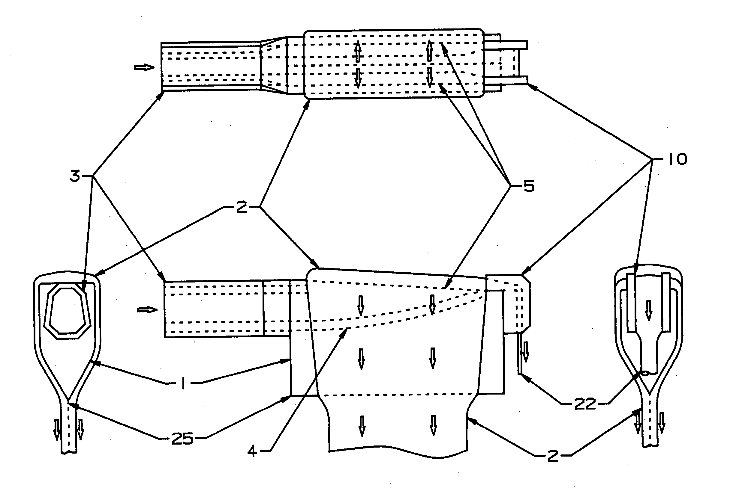
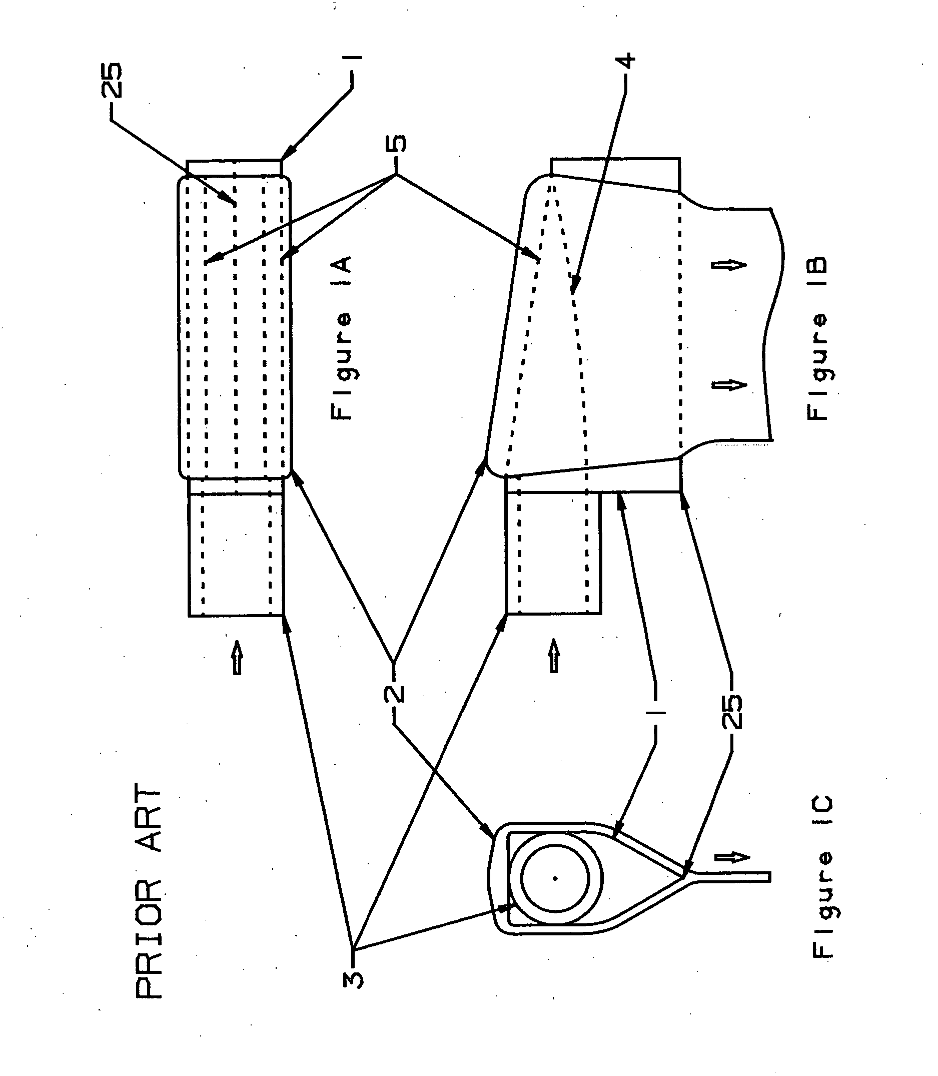
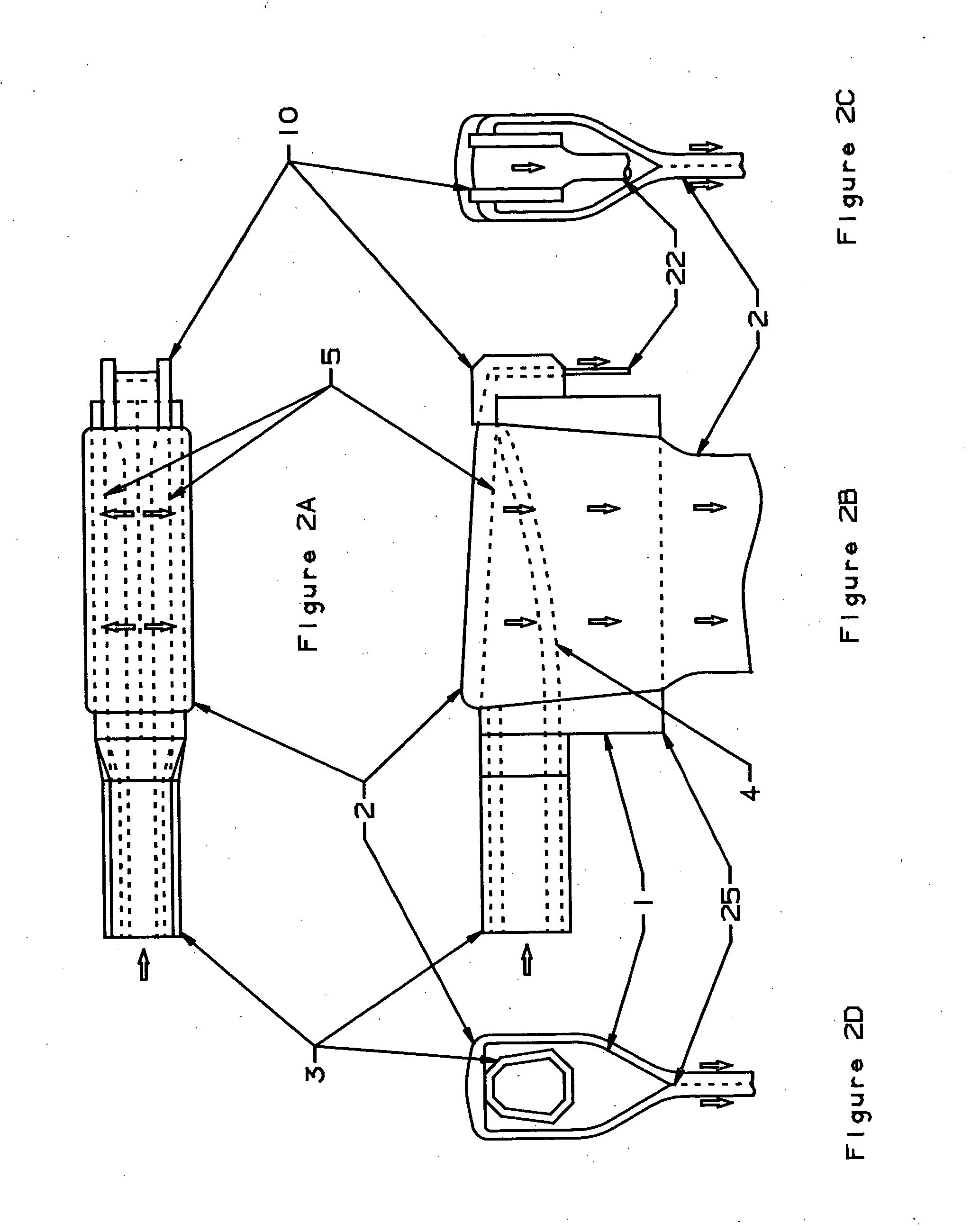
The present invention teaches that faster, more uniform flow of glass can be accomplished in the overflow glass process by modifying the forming apparatus in substantial ways. This process is currently used for making glass sheets that go into TFT / LCD display devices.

The glass must have very high surface quality, and sheet glass made using the overflow process has this quality. The overflow process is defined as a process that: 1) moves molten glass into a trough; 2) allows the glass to overflow the sides of the trough; and 3) the glass overflowing each side comes together such that the outside surface of the glass sheet is formed from glass that has not touched the surface of the glass forming equipment (post mixing). This untouched, “virgin glass”, forms an extremely uniform and clean outside surface of the glass sheet. Any modifications to the process or apparatus must provide this high quality glass surface.

The flow dynamics in all embodiments of this invention are such tha...


PUM

PropertyMeasurementUnit
static pressureaaaaaaaaaa
thicknessaaaaaaaaaa

Abstract

The forming apparatus of the present invention preferably includes an orifice on top of the trough. The uniquely shaped orifice substitutes for the weirs as the controlling entity for glass thickness. The orifice is designed such that as it deforms, it maintains a linear flow characteristic with respect to its length. As the orifice is made larger by the applied stress, the percentage width increase is the same over its length and consequently the percentage flow increase is the same over the length of the orifice. In another embodiment, the present invention provides an adjustment to change the flow characteristics of the trough to compensate for the degradation of the forming trough during an extended production run. A flow control plug can be inserted into the trough, such that flow dynamics can be altered during hot operation by insertion, removal or position adjustment of the flow control plug.

Description

BACKGROUND OF THE INVENTION 1. Field of the Invention The invention pertains generally to the manufacture of glass sheets, and, more particularly to a glass sheet formed from an overflow process. 2. Description of Related Art This invention relates to the manufacture of glass sheet that is currently used for the production of TFT / LCD display devices that are widely used for computers now and are expected to be used for television sets in the future. The glass that is used for these semiconductor powered display applications must have very high surface quality to allow the successful application of semiconductor type material. Sheet glass made using the apparatus of U.S. Pat. No. 3,338,696, incorporated herein by reference, makes the highest quality glass as formed and does not require post-processing. The patent teaches a manufacturing process termed: “the overflow process”. Glass made using other processes requires grinding and / or polishing and thus does not have as fine a sur...

Claims


Application Information

Patent Timeline
Patent Type & Authority Applications(United States)
IPC IPC(8): C03B17/06
CPCC03B17/064
Inventor PITBLADDO, RICHARD B.
Owner CORNING INC
Why Eureka
Try Eureka