Transportation system

a transportation system and mass transit technology, applied in the field of mass transit systems, can solve the problems of inability to meet the needs of vehicles, so as to reduce the drag of vehicles, reduce the force of the support system, and limit the ability of rails and rollers

Active Publication Date: 2005-04-14
TUBULAR RAIL INC
View PDF9 Cites 25 Cited by
  • Summary
  • Abstract
  • Description
  • Claims
  • Application Information

AI Technical Summary

Benefits of technology

[0013] The rings are large enough to enclose the diameter of the vehicle, about 20 feet in diameter in the preferred embodiment. The pedestal is preferably about 16 feet high, or more, to provide adequate clearance for any automobile or other wheeled vehicle traveling on a roadway underneath the line of travel of the vehicle of the present invention. The pedestal is mounted to a robust base structure, which may extend, for example, 30 feet below the surface of the ground, in order to provide sufficient margin for the strength of the support system.
[0014] The present invention also includes an e

Problems solved by technology

In the United States, modes of travel between cities offer few options, typically by air, bus, personal automobile, and to a limited extent by conventional rail.
A major drawback in such conventional rail systems lies in the exorbitant costs of building, maintaining, and operating such systems.
The initial cost of building a high-speed, conventional rail system can run into literally billions of U.S. dollars, depending on the size of the rail system, the geographical obstacles that have to be overcome, and many other factors.
In fact, there is a real need for

Method used


Image

  • Transportation system
  • Transportation system
  • Transportation system

Examples


Embodiment Construction

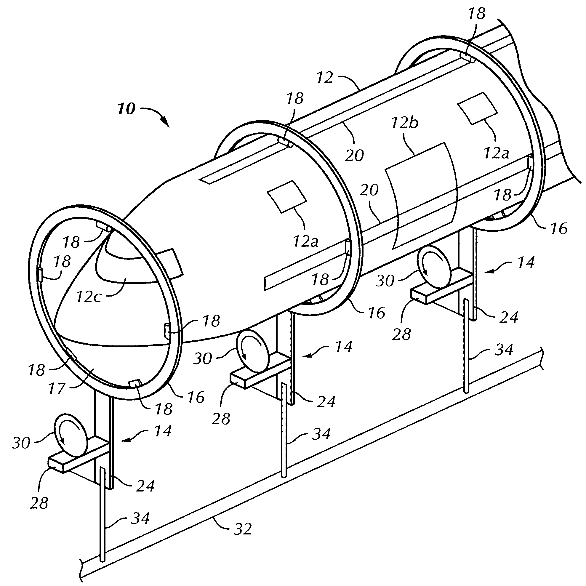
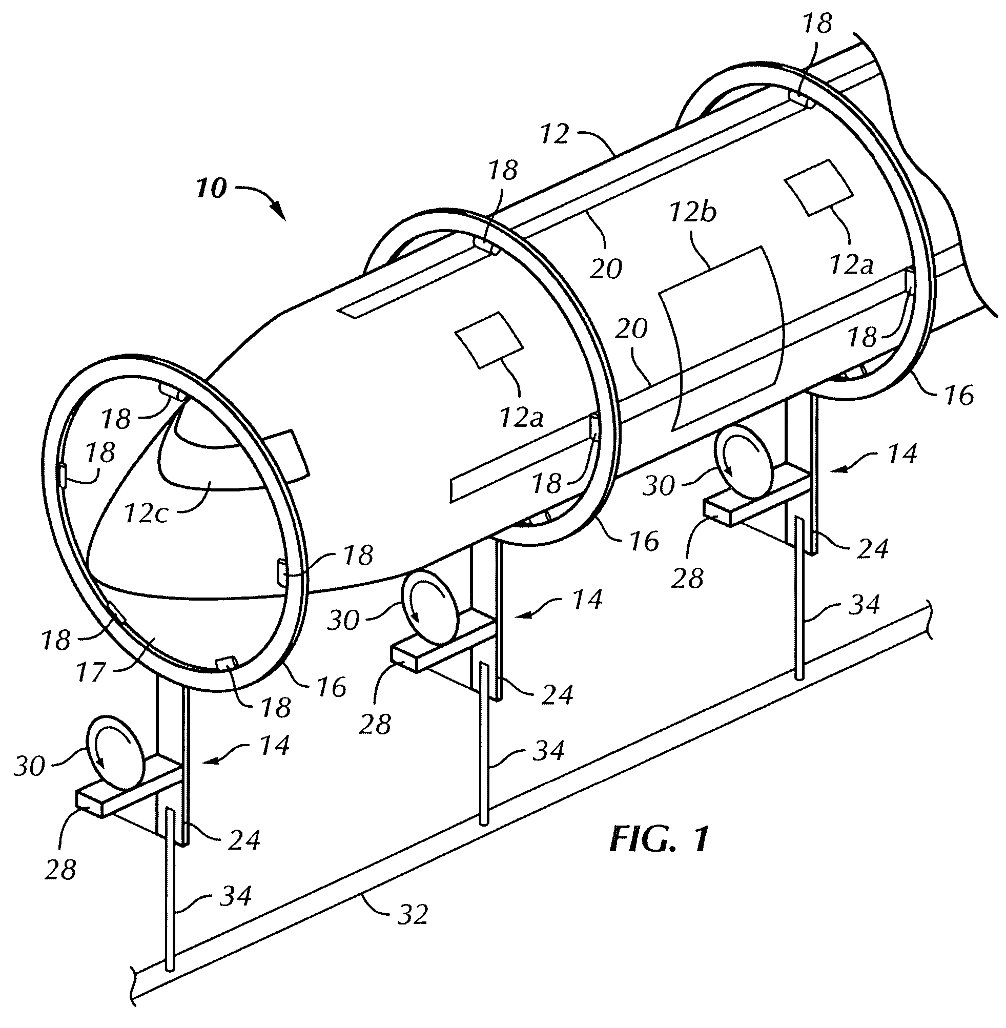
[0032]FIG. 1 depicts an overall schematic of a transportation system 10 constructed in accordance with this invention. The system 10 comprises an elongated car or vehicle 12 and a plurality of supports 14. The car or vehicle 12 may have suitable number of appropriately located windows 12a and doors 12b, and a cockpit 12c for an operator. If the vehicle is to be fully automated, the cockpit 12c may serve as an observation area for safety or emergency control purposes. The vehicle body 12 is presently contemplated to be a unitary structure or it may be an articulated body, if desired.

[0033] The supports 14 are arranged to define a route of travel along a desired course at an elevated height for transport of passengers and cargo. In a contemplated embodiment, the vehicle 12 is about 500 feet long, and the supports are about 200 feet apart, so that there are typically at least two, and optionally three or more, supports 14 in contact with a vehicle 12 at any time. The spacing of the su...


PUM


Abstract

A mass transit system includes a plurality of pedestal-mounted rings which provide a support through which a vehicle travels. The pedestals are spaced apart on the ground, but no rail or connecting structure on or above ground is required. An underground conduit carries electrical and communications cable that connects the pedestals together. The rings include a plurality of rollers to drive, guide and stabilize the vehicle at lower speeds. For higher speeds flywheels are mounted on the pedestals. The flywheels are preferably driven by an electrical motor, which engages a friction or clutch plate on the vehicle separate from the rings. The friction plate or linear clutch is mounted separate from the rings on the vehicle and is lowered to engage and disengage the flywheel. The flywheel is also mounted on a shock absorber to smooth the travel of the vehicle.

Description

[0001] This Application claims the benefit of U.S. Provisional Patent Application Ser. No. 60 / 506,896 filed Sep. 29, 2003.BACKGROUND OF THE INVENTION [0002] 1. Field of the Invention [0003] The present invention relates generally to the field of transportation systems and, more particularly, to a mass-transit system including a plurality of pedestal mounted rings to guide and propel an elongated vehicle carrying passengers, cargo, and the like. [0004] 2. Background of the Invention [0005] Transportation of people and cargo has become increasingly important in our modem lives. In the United States, modes of travel between cities offer few options, typically by air, bus, personal automobile, and to a limited extent by conventional rail. Other countries in the world, most notably Japan and France, have developed high speed rail systems between major destinations, but these systems rely for the most part on conventional rail infrastructure with some technological improvements in the rai...

Claims


Application Information

Patent Timeline
IPC IPC(8): B61B5/00B61B13/00B61B13/12B61FE04H12/00
CPCB61B13/00Y02T30/30B61B13/127Y02T30/00
Inventor PULLIAM, ROBERT C.
Owner TUBULAR RAIL INC
Why Eureka
Try Eureka