
Hybrid sphere-waveguide resonators

a waveguide and sphere technology, applied in the field of optical devices, can solve the problems of difficult to achieve the fiber-microsphere combination described above, difficult to achieve the free sphere and thinned fiber, and relatively long (a few cm), so as to increase the stability of the position of the microcavity, facilitate the launch, and reduce the effect of the cavity q

Inactive Publication Date: 2005-04-14
3M INNOVATIVE PROPERTIES CO
View PDF45 Cites 63 Cited by
  • Summary
  • Abstract
  • Description
  • Claims
  • Application Information

AI Technical Summary

Benefits of technology

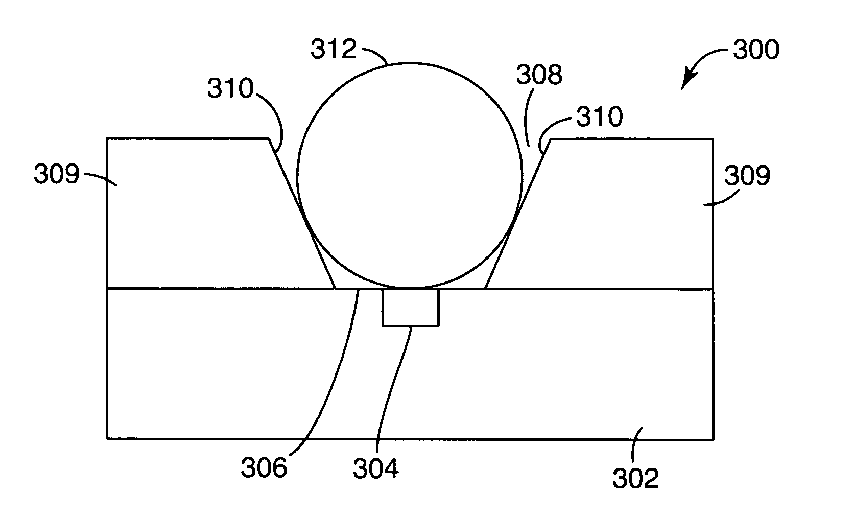
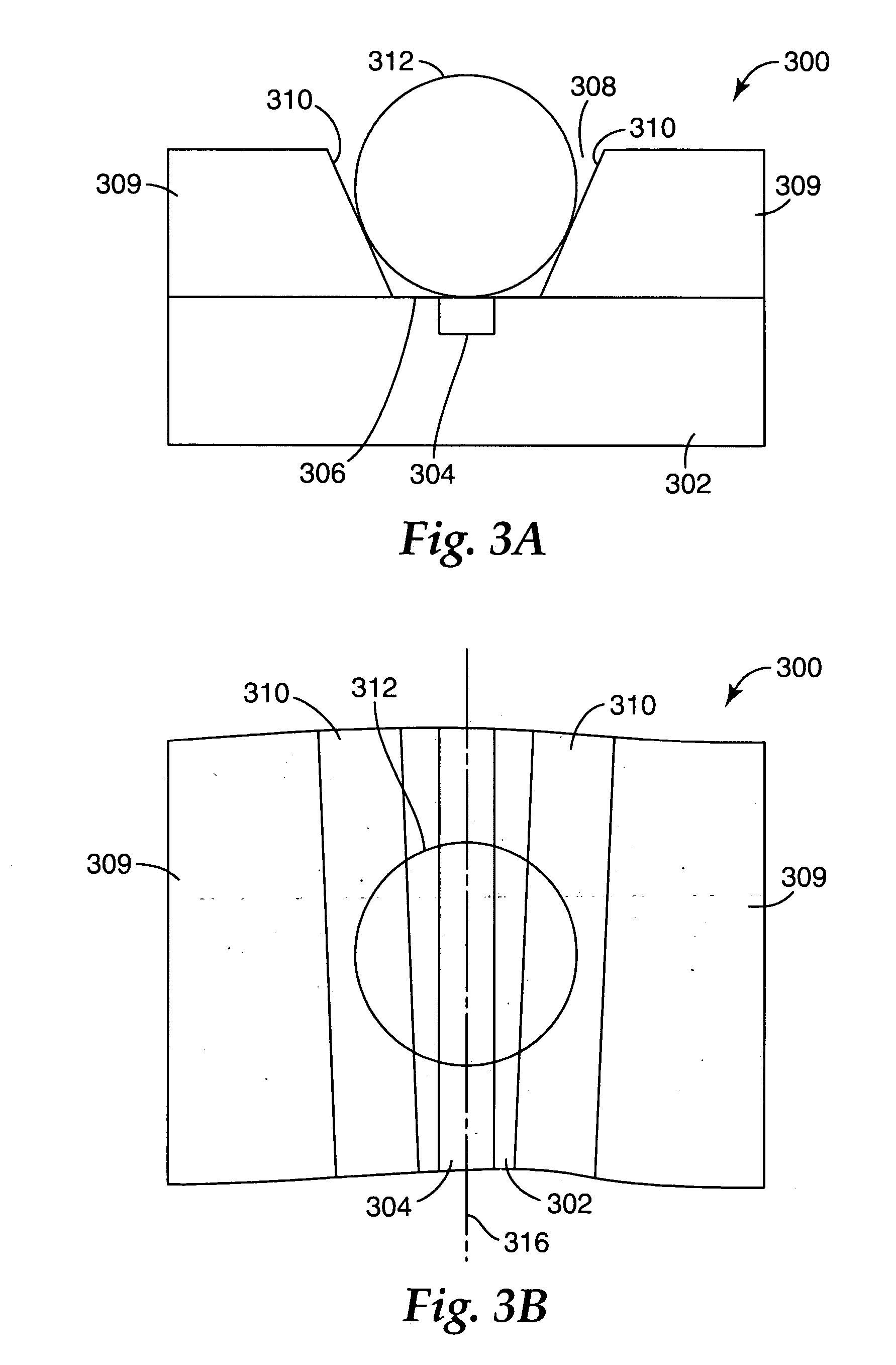
The patent text describes a need to increase the stability of a microcavity's position in relation to a waveguide, while maintaining high cavity quality and ease of launching and extracting optical beams. The invention provides structures on a substrate that help achieve this. One embodiment involves a microresonator device that includes a self-aligning feature on a substrate and a waveguide, with the microresonator positioned to optically couple with the waveguide. Another embodiment involves a method of making a microresonator optical device, which involves using a self-aligning feature to position the microresonator in relation to the waveguide. Overall, the invention provides a solution for improving the stability of microcavity positioning in optical devices.

Problems solved by technology

There are practical difficulties in realizing the fiber-microsphere combination described above.
This commonly results in a relatively long (a few cm) and fragile tapered region.
This is difficult with a free sphere and thinned fiber.
The etching process used to fabricate the disk resonator, however, invariably introduces surface roughness, that results in a scattering loss that severely degrades the Q of the cavity.
This approach preserves the high Q-factor of the glass microsphere, but does not solve the problem of how to precisely control the coupling between the microsphere and the waveguide.

Method used


Image

  • Hybrid sphere-waveguide resonators
  • Hybrid sphere-waveguide resonators
  • Hybrid sphere-waveguide resonators

Examples


Embodiment Construction

The present invention is applicable to passive and active optical devices, such as sensors, filters, amplifiers, and / or micro-lasers, that use microresonators, such as microspheres and micro-planar ring cavities. The invention is believed to be particularly useful for fabricating such devices, in that the relative positions of the microresonator and the waveguide are controlled, the microresonator Q-factor can be high, and there is ease in launching and receiving the optical beam.

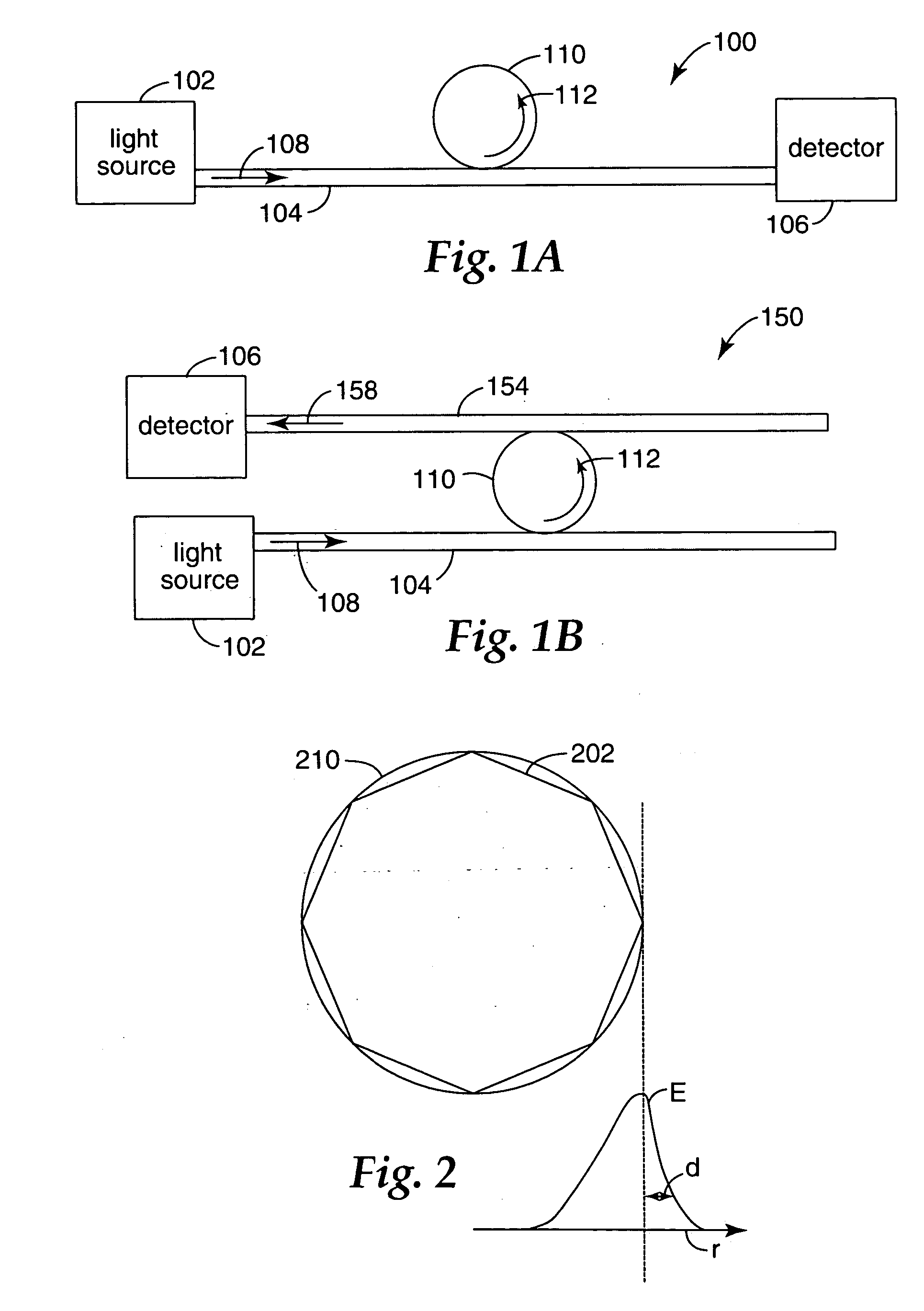
A microsphere-waveguide system 100 that uses a microresonator is schematically illustrated in FIG. 1A. A light source 102 directs light along a waveguide 104 to a detector unit 106. The microresonator 110 is optically coupled to the waveguide 104. Light 108 from the light source 102 is launched into the waveguide 104 and propagates towards the detector unit 106. The microresonator 110 evanescently couples some of the light 108 out of the waveguide 104, the out-coupled light 112 propagating within the mic...


PUM

PropertyMeasurementUnit
thicknessaaaaaaaaaa
diameteraaaaaaaaaa
optical couplingaaaaaaaaaa

Abstract

Microresonators, such as a microsphere resonators and planar microresonators, are optically coupled to waveguides for input and output of light. It is important that the relative positions of the microresonator and the waveguide are maintained stable, while still maintaining high cavity Q and ease of launching and extracting the optical beams. Structures are provided on a substrate that are useful for maintaining the position of the microresonator relative to the waveguide. The structures provide for vertical or horizontal coupling between the waveguide and the microresonator.

Description

FIELD OF THE INVENTION The present invention is directed generally to optical devices, and more particularly to passive and active optical devices such as optical sensors, filters and micro-lasers, based on microresonators. BACKGROUND Dielectric microresonators have attracted increasing attention in opto-electronic and sensing applications, including biosensing. One common configuration of microresonator involves a glass microsphere, typically 20 μm to a few millimeters in diameter, which is put into close proximity to an optical waveguide such as an optical fiber that has been heated and tapered, or etched to a total thickness of 1-5 μm. The tapering modifications to the fiber result in there being a substantial optical field intensity outside the fiber, and thus light can couple into the microsphere and excite its eigenmodes, often referred to as whispering gallery modes (WGMs). When microresonators are made with low loss materials and have a high surface quality, the propagati...

Claims


Application Information

Patent Timeline
Patent Type & Authority Applications(United States)
IPC IPC(8): G01N21/55G01N21/64G01N21/77G02B6/10G02B6/12G02B6/26G02B6/28G02B6/34G02B6/36
CPCG01N21/552G01N21/645G01N21/648G01N21/7746G01N2021/6484G02F2203/15G02B6/26G02B6/29341G02B6/3652G02B6/3692G02B6/4246G02B6/12007
Inventor FAN, XUDONGPOTTS, JOHN E.SMITH, TERRY L.WILSON, ROBERT W.
Owner 3M INNOVATIVE PROPERTIES CO
Learn More