Scanning microscope

a scanning microscope and microscope technology, applied in the field of scanning microscopes, can solve the problems of long physical length, inability to detect the wavefront of the stimulation light beam,

Inactive Publication Date: 2005-04-14
LEICA MICROSYSTEMS CMS GMBH
View PDF10 Cites 29 Cited by
  • Summary
  • Abstract
  • Description
  • Claims
  • Application Information

AI Technical Summary

Benefits of technology

[0016] It is therefore an object of the present invention to provide a scanning microscope that, with a simple and compact construction, establishes the correct time offset of the first and second light pulses.

Problems solved by technology

The known arrangements have on the one hand the disadvantage of a very long physical length, since a light path of several meters must be provided in order to achieve sufficient delaying of the light pulses of the stimulation light beam with respect to the light pulses of the excitation light beam, and on the other hand the disadvantage that the gratings used to stretch out the pulse duration of the light pulses of the stimulation light beam largely destroy the wavefront of the stimulation light beam because of their inherently poor surface quality.

Method used


Image

  • Scanning microscope
  • Scanning microscope
  • Scanning microscope

Examples


Embodiment Construction

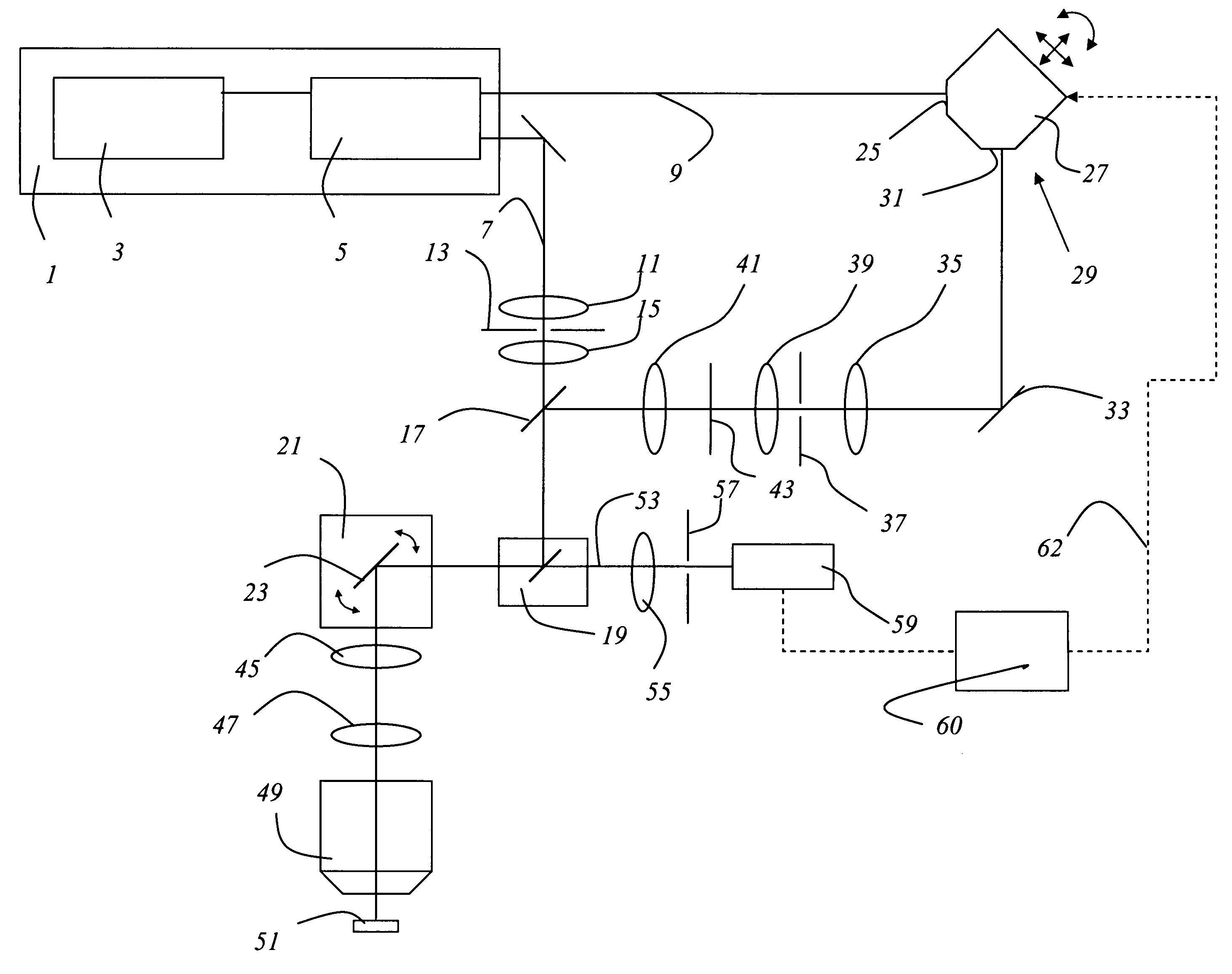
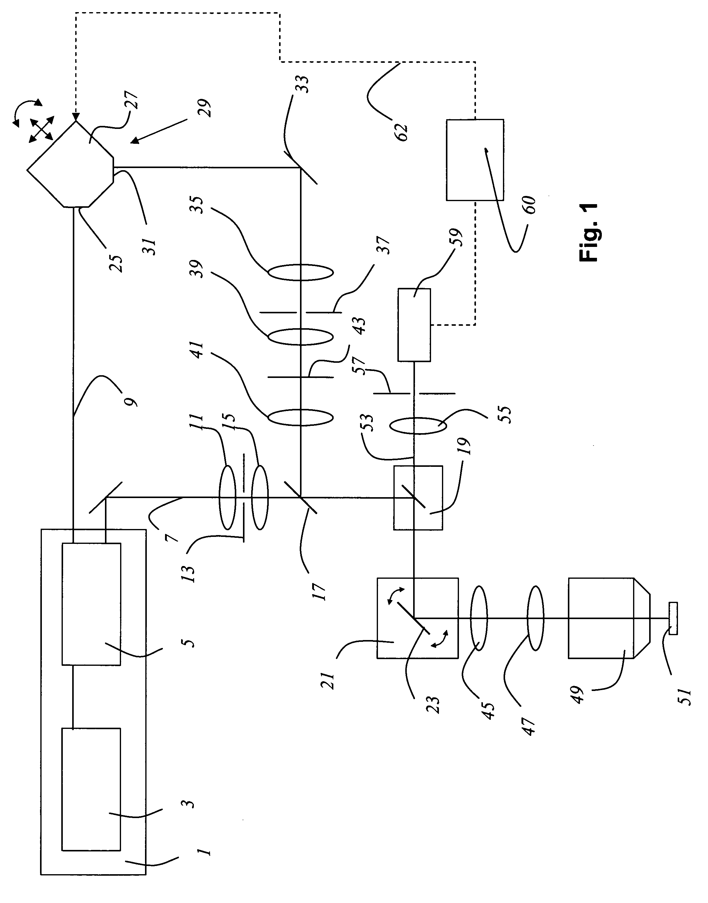
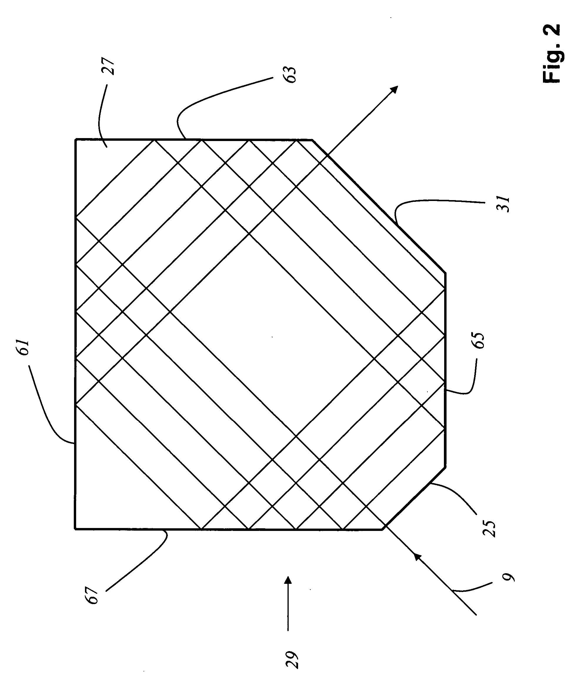
[0032]FIG. 1 shows a scanning microscope according to the present invention having a light source 1 that contains a primary laser 3 and an optically parametric oscillator 5. Light source 1 emits an excitation light beam 7 and a stimulation light beam 9, which are both pulsed and have different wavelengths. Excitation light beam 7 is focused with optical system 11 onto illumination pinhole 13, then collimated by optical system 15 and, after traversing beam combiner 17, strikes main beam splitter 19 that directs excitation light beam 7 to a beam deflection device 21 which contains a gimbal-mounted scanning mirror 23. Stimulation light beam 9 is coupled through an incoupling window 25 into a dispersive medium 29 embodied as a glass block 27, passes through the latter several times, and leaves it through outcoupling window 31. Stimulation light beam 9 is then directed by a mirror 33 through focusing optical system 35 onto stimulation pinhole 37. Stimulation light beam 9 then passes thro...


PUM


Abstract

In a scanning microscope that impinges upon a sample with a first light pulse and a second light pulse, a dispersive medium that modifies the time offset between the first and the second light pulse is provided in the beam path of at least one of the light pulses.

Description

CROSS REFERENCE TO RELATED APPLICATIONS [0001] This application claims priority to German patent application 103 47 712.8, the subject matter of which is hereby incorporated by reference herein. FIELD OF THE INVENTION [0002] The invention concerns a scanning microscope that impinges upon a sample with a first light pulse and a second light pulse. BACKGROUND OF THE INVENTION [0003] In scanning microscopy, a sample is illuminated with a light beam in order to observe the reflected or fluorescent light emitted from the specimen. The focus of an illuminating light beam is moved in a specimen plane by means of a controllable beam deflection device, generally by tilting two mirrors, the deflection axes usually being perpendicular to one another so that one mirror deflects in the X direction and the other in the Y direction. Tilting of the mirrors is brought about, for example, by means of galvanometer positioning elements. The power level of the light coming from the specimen is measured ...

Claims


Application Information

Patent Timeline
Patent Type & Authority Applications(United States)
IPC IPC(8): G02B21/00G02B21/06G02B21/16
CPCG02B21/0032G02B21/16G02B21/06G02B21/0084
Inventor GUGEL, HILMAR
Owner LEICA MICROSYSTEMS CMS GMBH
Why Eureka
Try Eureka