Plasma display apparatus
- Summary
- Abstract
- Description
- Claims
- Application Information
AI Technical Summary
Benefits of technology
Problems solved by technology
Method used
Image

Examples
first embodiment
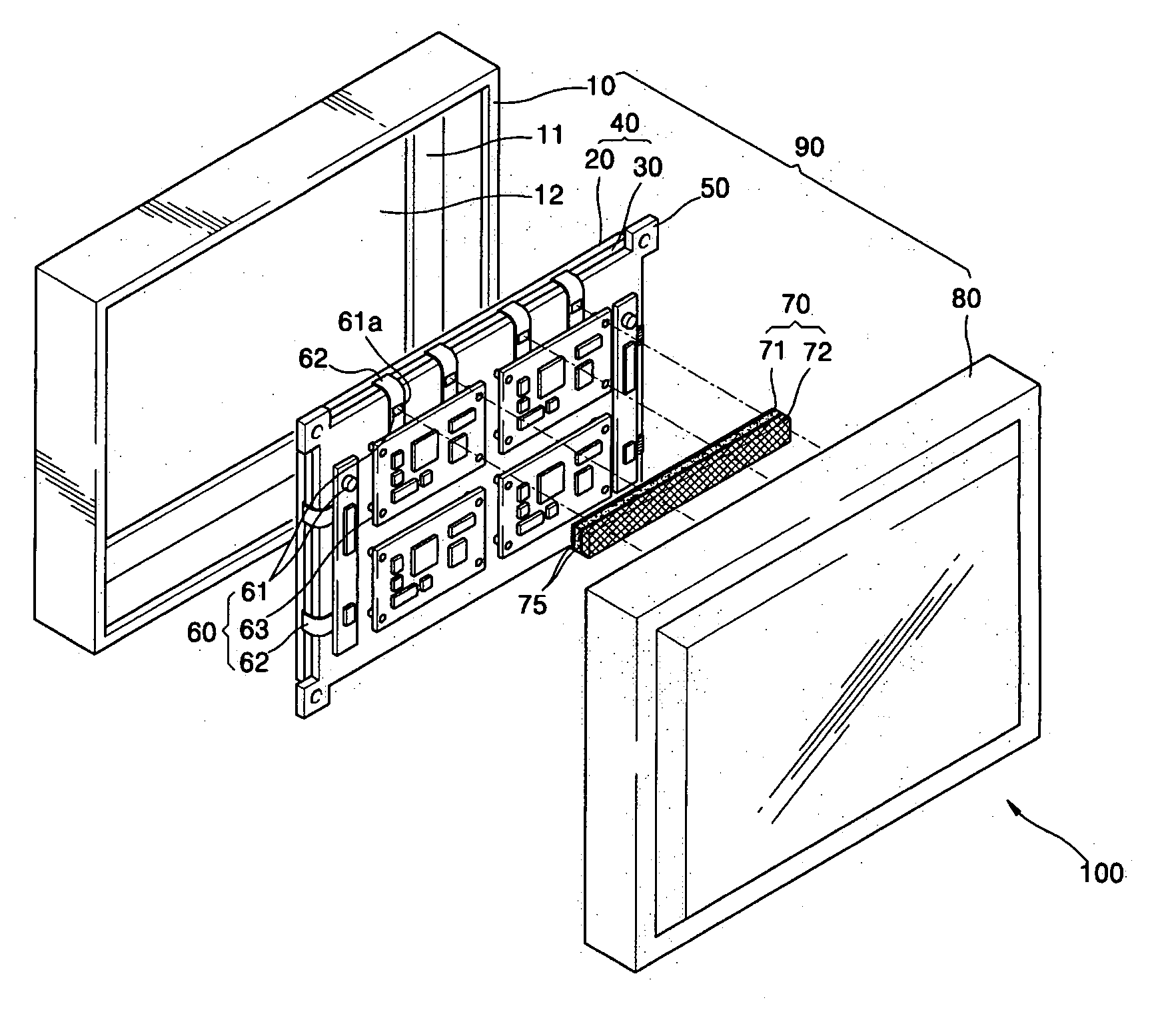
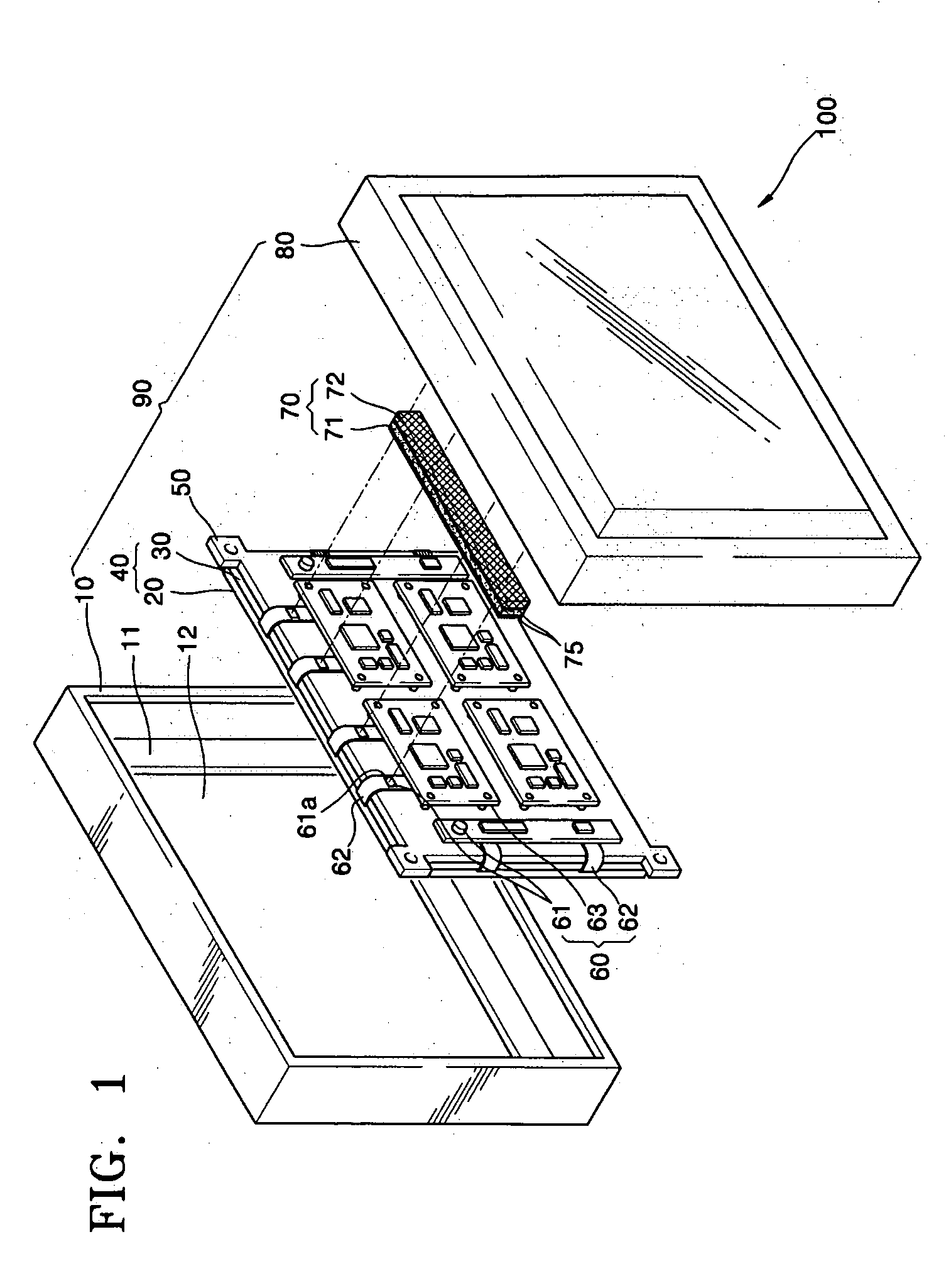
[0040]FIG. 1 is an exploded perspective view of a plasma display apparatus according to the present invention. FIG. 2 is a partial perspective view of the plasma display apparatus of FIG. 1, and FIG. 3 is a cross-sectional view of the plasma display apparatus of FIG. 1.
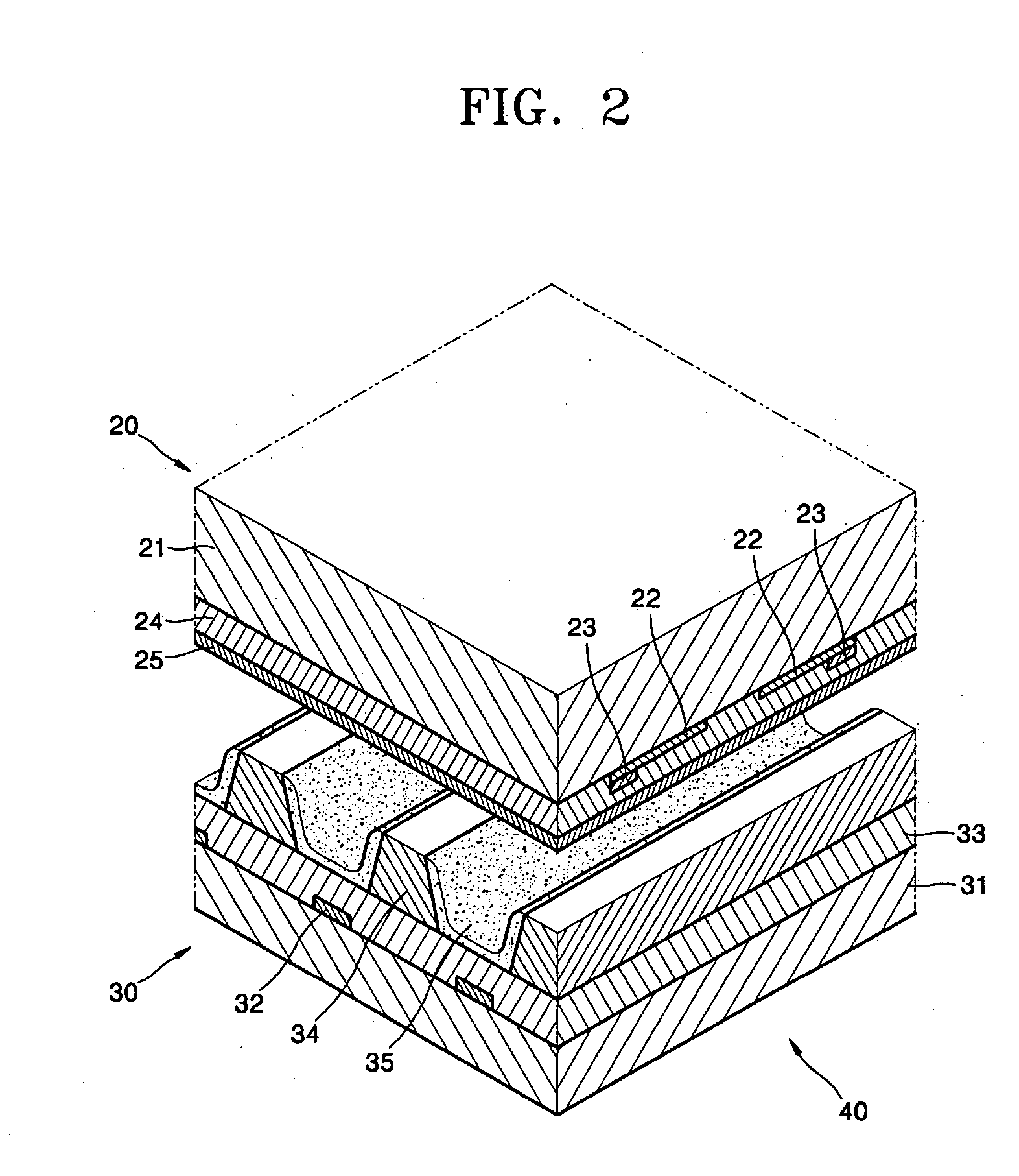
[0041] Referring to FIG. 1, a plasma display apparatus includes a PDP 40, a chassis base 50, a circuit section 60, and a cabinet 90. Referring to FIG. 2, the PDP 40 includes a first panel 20 and a second panel 30 combined together.
[0042] The first panel 20 on which an image will be displayed includes a first substrate 21, discharge sustain electrodes 22, bus electrodes 23, a first dielectric layer 24, and a protective layer 25.
[0043] The discharge sustain electrodes 22 are arranged in a predetermined pattern, such as a stripe pattern under the first substrate 21.
[0044] The discharge sustain electrode 22 may be composed of a transparent material such as indium tin oxide (ITO) for transmitting discharged visible ligh...
second embodiment
[0068]FIG. 5 is a cross-sectional view of a plasma display apparatus of the present invention. Referring to FIG. 5, a heat dissipation means 70 includes a first heat transfer medium 71, a second heat transfer medium 72, and a third heat transfer medium 73, and is interposed between driving devices 61a and back cover 80. The first and the third heat transfer mediums 71 and 73 are formed to have high flexibility and thermal conductivity, and the second heat transfer medium 72 is formed to have high thermal conductivity.
[0069] The first and the third heat transfer mediums 71 and 73 can be formed in a variety of types. That is, a matrix resin that contains a heat transfer filler, a thermal conductive container in which a liquid heat dissipation material or a thermal conductive powder is filled, or a stacked layer of carbon fibers.
[0070] The second heat transfer medium 72 can be a plate formed of aluminum, silver, copper, or nickel.
[0071]81 By disposing the first and the third heat tr...
third embodiment
[0072]FIG. 6 is a partial sectioned view of a plasma display apparatus according to the present invention. Referring to FIG. 6, a heat dissipation means 70 of the driving device 61a includes first and second heat transfer mediums 71 and 72. The first heat transfer medium 71 has high flexibility and thermal conductivity and contacts the driving device 61a, and the second heat transfer medium 72 has high thermal conductivity and is interposed between the back cover 80 and the first heat transfer medium 71. The heat dissipation means 70 may be attached to the chassis base 50 by a thermal conductive adhesive 75.
[0073] As shown in FIG. 6, air holes 80a for improved air flow are formed on the back cover 80. When low temperature air from the outside enters the plasma display apparatus 100 through the air holes 80a, the temperature of the heat dissipation means 70 and the temperature of the chassis base 50 are reduced. Therefore, heat generated by the driving device 61a can be rapidly trans...
PUM
 Abstract
Description
Claims
Application Information
 - Generate Ideas
- Intellectual Property
- Life Sciences
- Materials
- Tech Scout
- Unparalleled Data Quality
- Higher Quality Content
- 60% Fewer Hallucinations
Browse by: Latest US Patents, China's latest patents, Technical Efficacy Thesaurus, Application Domain, Technology Topic, Popular Technical Reports.
© 2025 PatSnap. All rights reserved.Legal|Privacy policy|Modern Slavery Act Transparency Statement|Sitemap|About US| Contact US: help@patsnap.com