Distortion tolerant linear phase modulations

a phase modulation and distortion-tolerant technology, applied in phase-modulated carrier systems, digital transmission, baseband system details, etc., can solve the problems of large degradation of signal-to-noise power ratio for bit error performance, non-negligible distortion, etc., to achieve the maximum signal-to-distortion power ratio, the effect of maximizing the signal-to-distortion power ratio and reducing the loss of signal

Inactive Publication Date: 2005-04-14
LIU QINGCHONG
View PDF9 Cites 25 Cited by
  • Summary
  • Abstract
  • Description
  • Claims
  • Application Information

AI Technical Summary

Benefits of technology

This invention provides a novel method and system for signal and information, transmission which can overcome the distortion caused by RF circuits including power amplifiers and up-converters and mixers or by communication channels. Such power amplifiers can be in the class-C, class-D, class-E, class-F, or any of class-A and class-B and class-AB working in the saturation region. The invented method generates phase modulated signals in baseband and maximizes the signal-to-distortion power ratio at the output of the power amplifier or at the channel output. The maximization of the signal-to-distortion power ratio can be achieved using optimal filtering in base band. The invented filtering can be implemented using linear filter of finite impulse response or nonlinear filter. In the receiver, the invention uses a filter or filters matched to the base band filter or filters in

Problems solved by technology

These power amplifiers cause non-negligible distortion to linear phase modulations and are traditionally not used in systems which employ non-constant envelope phase modulations such as phase shift k

Method used


Image

  • Distortion tolerant linear phase modulations
  • Distortion tolerant linear phase modulations
  • Distortion tolerant linear phase modulations

Examples


Embodiment Construction

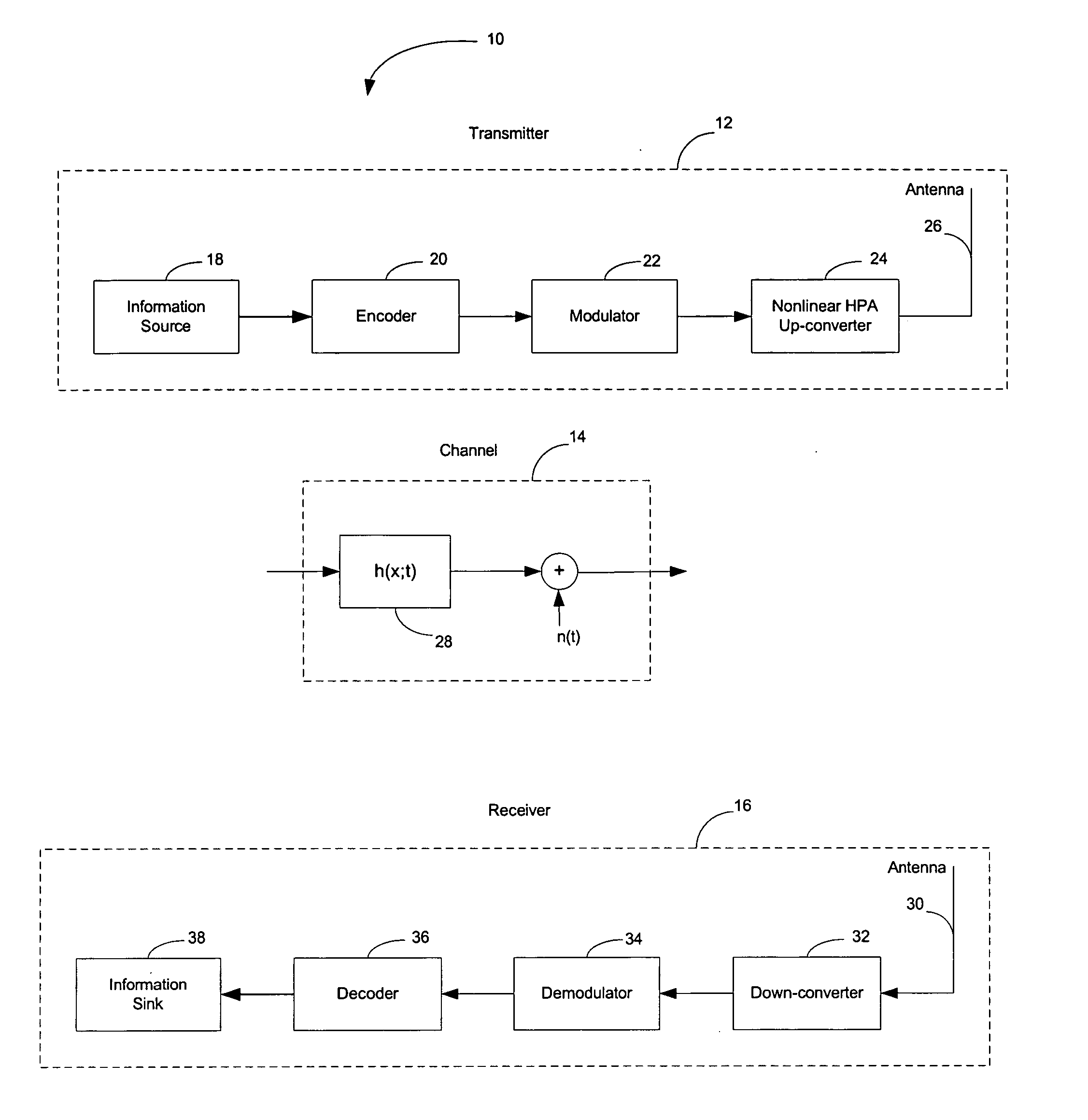
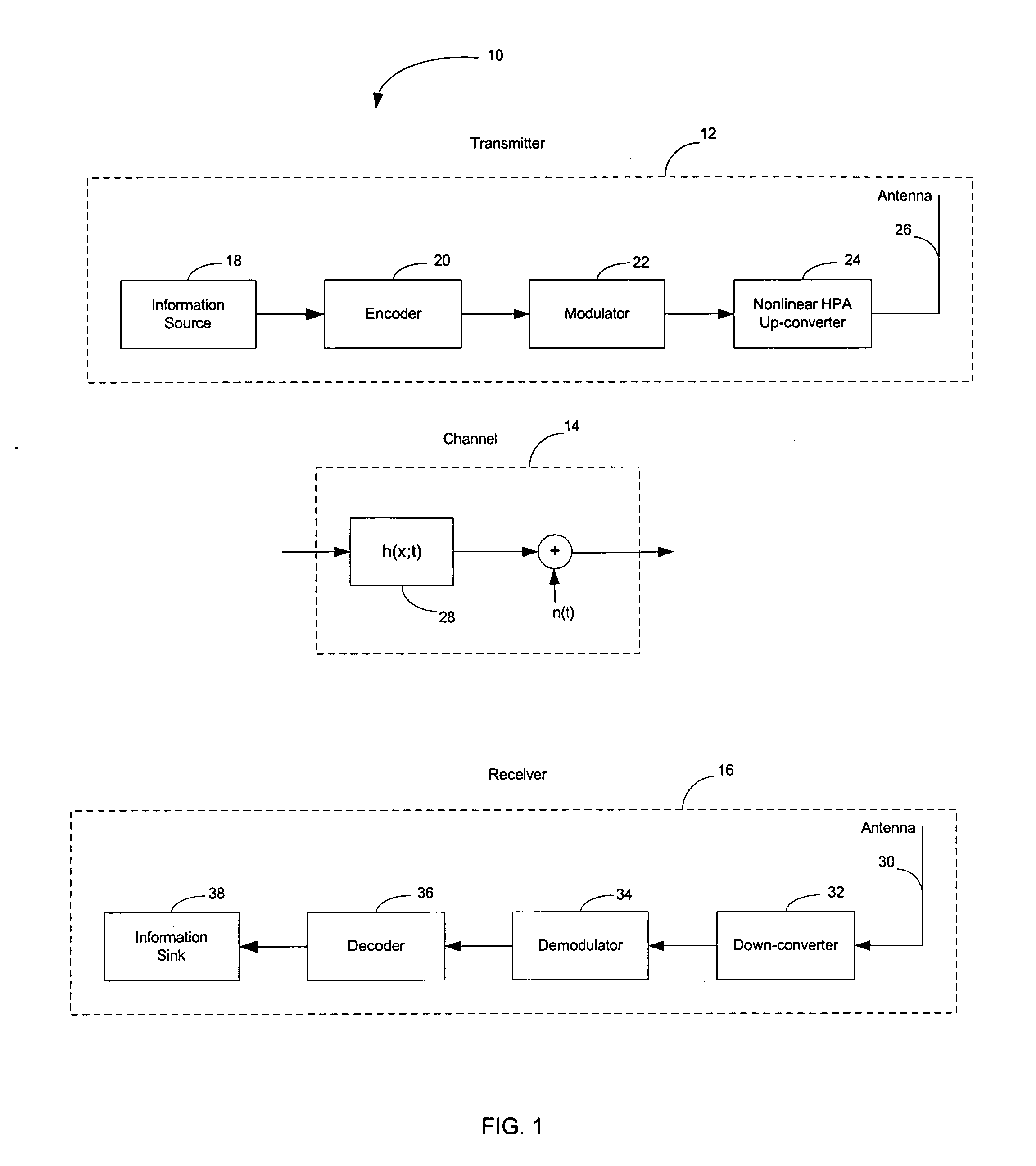
Referring to FIG. 1, a wireless communications system 10 in accordance with one embodiment of the present invention is illustrated. The system 10 includes a transmitter 12, a channel 14 and a receiver 16. The transmitter is in communication with the receiver in radio frequency (RF) through the channel.

The transmitter 12 has an information source 18, an encoder 20, a modulator 22, a high-power amplifier (HPA) with up-converter 24 and an antenna 26. The encoder performs encoding, which not only takes care of the additive noise in the channel but also overcomes the distortion. The distortion can be caused by either the high power amplifier and the up-converter with mixer 24 or the channel 14. The modulator 22 generates a modulated signal using phase shift keying. When the modulated signal is amplified and up-converted, the distortion at the output of the high power amplifier and up-converter 24 is minimized. The output signal of the high power amplifier and up-converter is fed into ...


PUM


Abstract

A signal and information transmission system for communications or radar and a method of achieving distortionless transmission of linear phase shift keying signals amplified by nonlinear power amplifiers or distorted by up-converters and RF circuits or the channel. Error correcting codes are used to jointly overcome both the distortion by the power amplifiers or up-converters and RF circuits or the channel and the noise. The modulator generates properly pulse shaped PSK signal, which does not have constant envelope. The signal-to-distortion power ratio is maximized to be above 20 dB at the fully saturated power amplifier output. The simplest linear receiver is provided to demodulate the received signal in the presence of radio distortion, channel distortion and noise. The decoder makes decision in the presence of radio distortion, channel distortion and noise. The method guarantees distortionless transmission of PSK signals for communications systems or radar employing power amplifiers of high DC-to-AC power conversion efficiency including class-F, class-E, class-D, class-C, or any of class-A, class-B, class-AB working in the saturation region. The method can achieve high bandwidth efficiency.

Description

BACKGROUND OF THE INVENTION 1. Field of the Invention The present invention relates to generating a linearly modulated signal using phase shift keying, which can tolerate distortion in transmission, and achieving optimal or near optimal demodulation performance in the presence of distortion. The distortion can be caused by RF circuits including high power amplifiers and up-converters and mixers at radio frequency or by the channel. The invention may have applications in communications systems using phase shift keying, wireless communications, satellite communications, radar, and in particular in a communication terminal or radar which needs enough transmission power, or high DC-to-AC power conversion efficiency, or simple design for transmitter or receiver, or simple radio frequency circuit design. 2. Background and Description of Related Art In recent years the data rate demanded for wireless communications has increased dramatically. Commercial products supporting 1 Gbps are a...

Claims


Application Information

Patent Timeline
IPC IPC(8): H04K1/02H04L27/18
CPCH04L27/18
Inventor LIU, QINGCHONG
Owner LIU QINGCHONG
Why Eureka
Try Eureka