Electrode array for use in electrochemical cells

a technology of electrochemical cells and electrode arrays, applied in the direction of wound/folded electrode electrodes, cell components, sustainable manufacturing/processing, etc., can solve the problems of increasing electrical leakage, undesirable effect, difficult to achieve proximity with purely opposing electrodes, etc., to reduce leakage and esr, and reduce series resistance

Inactive Publication Date: 2005-04-14
BIOSOURCE INC
View PDF1 Cites 49 Cited by
  • Summary
  • Abstract
  • Description
  • Claims
  • Application Information

AI Technical Summary

Benefits of technology

[0013] An additional advantage of the present invention is that the electrode arrays may be lines, dots, or any other shapes that can be arranged in patterns with small distances between shapes or nonfacing or adjacent surfaces of each pair of electrodes, for example, less than 3 millimeters, thereby allowing construction of an electrode array containing anode-cathode pairs within a single sheet of material. Therefore, the electrode array sheet may comprise anode-cathode pairs to act as an integrated capacitor, electrochemical cell, or flow-through capacitor. These electrode array sheets, containing one or more anode-cathode pairs per sheet, may be stacked together in any geometry known to prior art flow-through capacitors, electrochemical cells, water filters, batteries, or electronic capacitors.
[0014] In one em...

Problems solved by technology

However, proximity is difficult to achieve with purely opposing electrodes.
In order to place the electrodes close together, for example, closer than 0.03 inches (˜760 μm), the dielectric between them must ...

Method used


Image

  • Electrode array for use in electrochemical cells
  • Electrode array for use in electrochemical cells
  • Electrode array for use in electrochemical cells

Examples


example 1

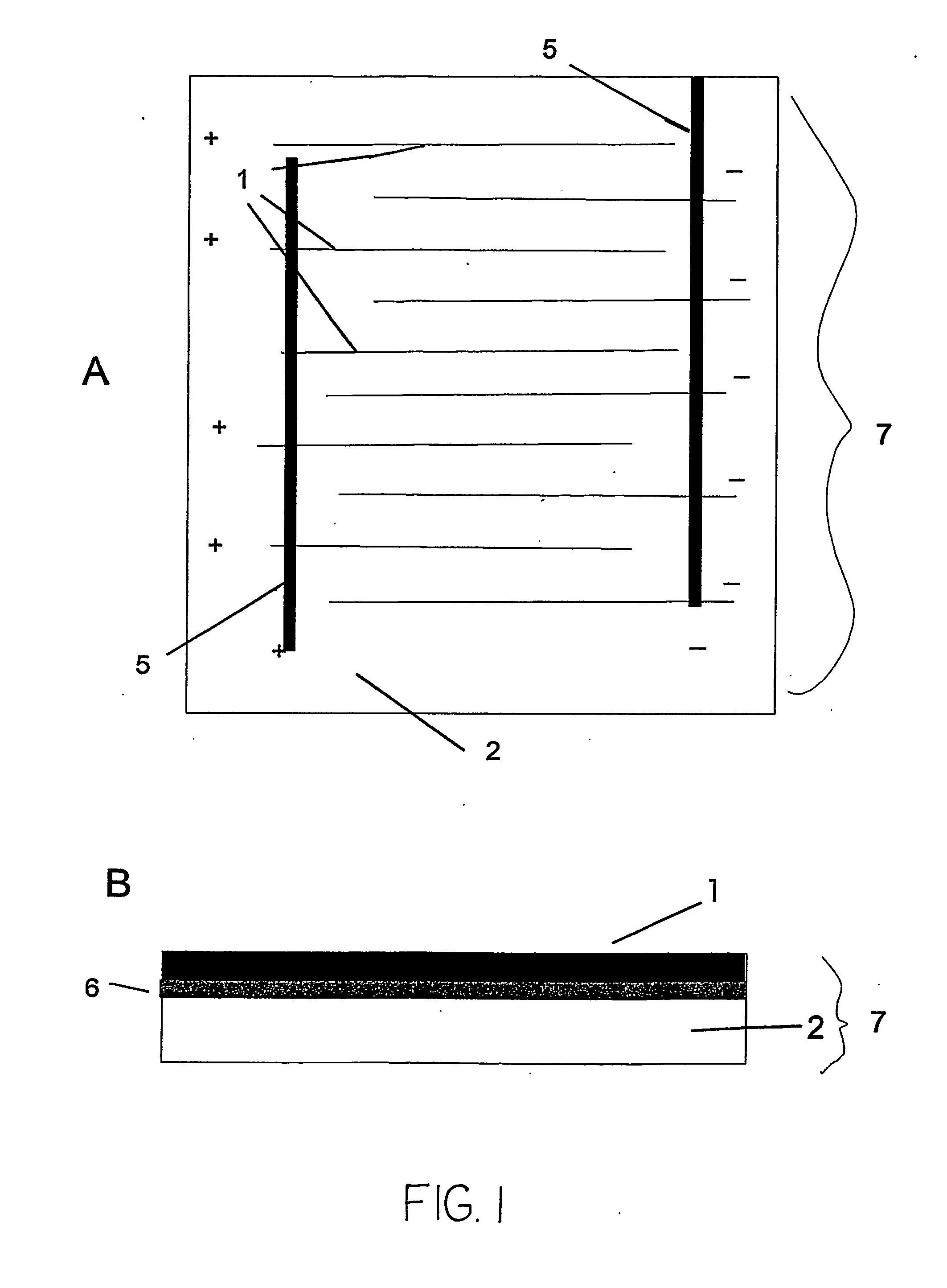
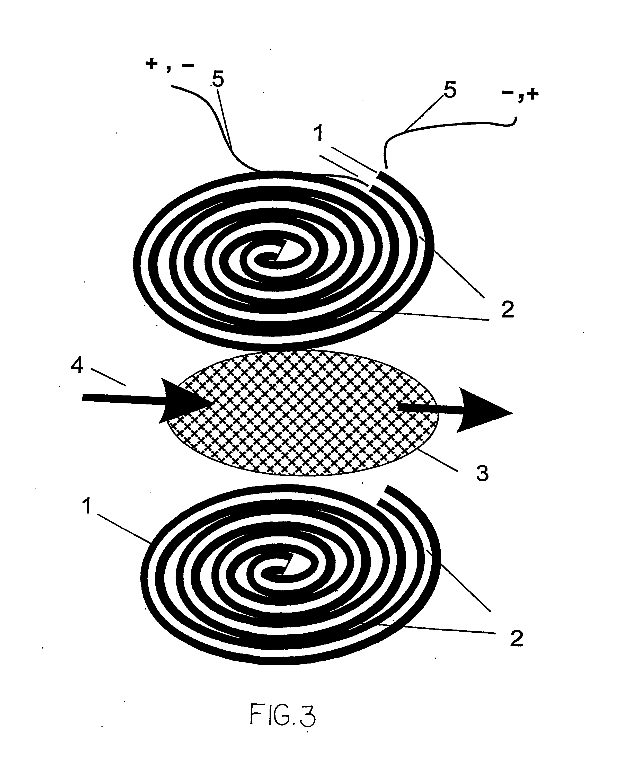
[0070] A thin sheet electrode array, under 0.1 inches thick, preferably under 0.02 inches thick, with alternating electrodes such as shown in FIG. 1 or 2, is placed against a flow spacer. One or more electrode array layers are placed together with the flow spacer in any geometry used in flow-through capacitors or electrochemical cells. The electrode array and flow channel layers may be held together or compressed between end plates in order to form a flow-through electrochemical cell. Inlet and outlet means are provided exactly as in any other parallel electrode prior art electrochemical cell. The difference in the present invention is that electrodes in any prior art electrochemical cell geometry are replaced by electrode arrays of the present invention. A separate layer of current collectors may be placed underneath the electrode material.

example 2

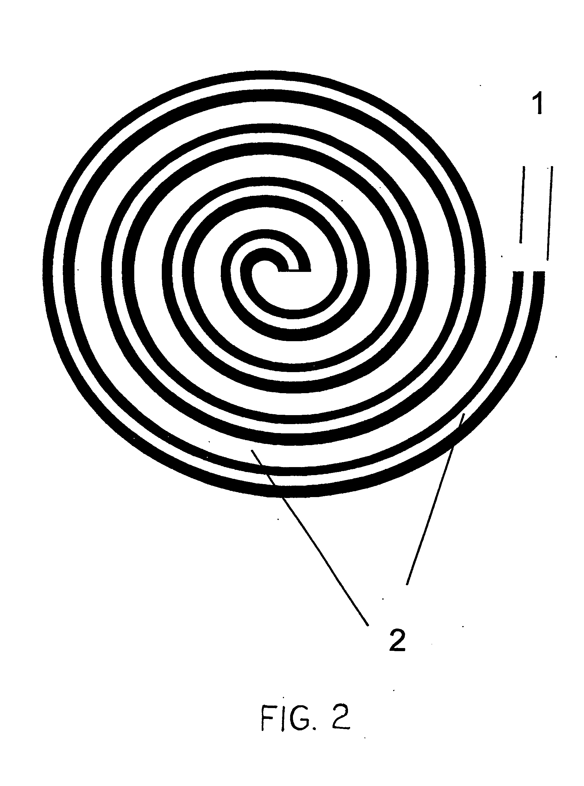
[0071] Carbon powder PTFE electrodes of 0.01 inch thick are laminated with a graphite current collector layer and a 0.001-inch thick, nonporous, polymer spacer on one or both sides of the electrode / current collector. Arrays of holes 0.005 inches wide, spaced 0.010-inch center to center, are cut through spacer, electrode, and current collector layers in order to form a thin sheet electrode array. This array may be spiral wound, stacked flat against, or laminated for use with a separator used to form a flow channel and formed into an electrochemical cell or flow-through capacitor of any prior art geometry, where the electrode array of the present invention replaces the electrode used in the prior art.

example 3

[0072] Carbon powder PTFE electrodes of 0.01 inch thick are laminated with a graphite current collector layer and a 0.001-inch thick, nonporous, polymer spacer on one or both sides of the electrode / current collector. This is subsequently stacked or rolled into a jelly roll and heat treated or glued together in order to bind the layers together into a monolith. The monolith may be a rectangle, or cylinder, or any other shape. The monolith is subsequently skived diagonally or perpendicularly across the layers in order to form thin electrode sheet arrays of the present invention for use in electrochemical cells or flow-through capacitors.


PUM


Abstract

The invention features an electrode array (7) in which pairs of electrodes (1) are geometrically arranged so that the broadest faces of the exposed electrodes are not directly opposing to each other. Rather, the broadest facing surfaces of the electrodes in the array are parallel, adjacent, or offset at an angle. The electrode geometry of an electrode array of the invention permits electrodes to be in close proximity, thereby lowering series resistance, while minimizing the possibility for short circuits that can cause electrical leakage. An electrode array of the invention can be used in an electrochemical cell, such as a battery, e.g., a lithium battery, a capacitor, a flow-through capacitor, or a fuel cell.

Description

REFERENCE TO PRIOR APPLICATION [0001] This application is based on and claims priority from U.S. Provisional Patent Application Ser. No. 60 / 307,789, filed Jul. 25, 2001, hereby incorporated by reference in its entirety.GOVERNMENT CONTRACT [0002] This invention was funded under contract with the Army Research Office, under Contract No. DDAD 19-00-C-0448. The United States Government may have certain rights in the invention.FIELD OF THE INVENTION [0003] The field of the invention is electrodes for electrochemical cells. BACKGROUND OF THE INVENTION [0004] In electrochemical cells, such as capacitors, batteries, fuel cells, and flow-through capacitors, it is desirable to reduce series resistance and electrical leakage, which waste energy. Normally, to reduce series resistance, it would be desirable place the electrodes close together. However, proximity is difficult to achieve with purely opposing electrodes. In order to place the electrodes close together, for example, closer than 0.03...

Claims


Application Information

Patent Timeline
IPC IPC(8): C02F1/461H01G9/00H01G9/155H01M2/02H01M2/18H01M4/00H01M4/36H01M6/08H01M6/40H01M10/04H01M10/052H01M10/058H01M10/0585H01M10/0587H01M10/36
CPCC02F1/46109Y02E60/13C02F2001/46133C02F2001/46152C02F2201/46195H01G9/155H01M6/10H01M6/40H01M10/0431H01M10/0436H01M10/052H01M10/058H01M10/0585H01M10/0587Y02E60/122C02F1/4691Y02E60/10Y02P70/50H01G11/82H01G11/26H01G11/14
Inventor ANDELMAN, MARC D.ZULKIEWICZ, JON
Owner BIOSOURCE INC
Why Eureka
Try Eureka