
Friction stir welding improvements for metal matrix composites, ferrous alloys, non-ferrous alloys, and superalloys using a superabrasive tool

a technology of friction stir welding and superabrasive tool, which is applied in the direction of welding devices, soldering devices, manufacturing tools, etc., to achieve the effects of improving friction stir welding, and improving the characteristics of cooled joints

Inactive Publication Date: 2005-04-21
MAZAK CORP +1
View PDF15 Cites 46 Cited by
  • Summary
  • Abstract
  • Description
  • Claims
  • Application Information

AI Technical Summary

Benefits of technology

[0012] It is another object to provide improved friction stir welding in various underwater environments.
[0021] It is another object to provide improved friction stir welding by providing an independently movable mandrel when friction stir welding pipe.

Problems solved by technology

While communication is obviously important, it is difficult when dealing with hazardous environments such as near a nuclear containment vessel.

Method used


Image

  • Friction stir welding improvements for metal matrix composites, ferrous alloys, non-ferrous alloys, and superalloys using a superabrasive tool
  • Friction stir welding improvements for metal matrix composites, ferrous alloys, non-ferrous alloys, and superalloys using a superabrasive tool
  • Friction stir welding improvements for metal matrix composites, ferrous alloys, non-ferrous alloys, and superalloys using a superabrasive tool

Examples


Embodiment Construction

[0044] Reference will now be made to the drawings of the invention in which the various elements of the present invention will be numbered and described so as to enable one skilled in the art to make and use the invention. It is to be understood that the following description is only exemplary of the principles of the present invention, and should not be viewed as narrowing the claims which follow.

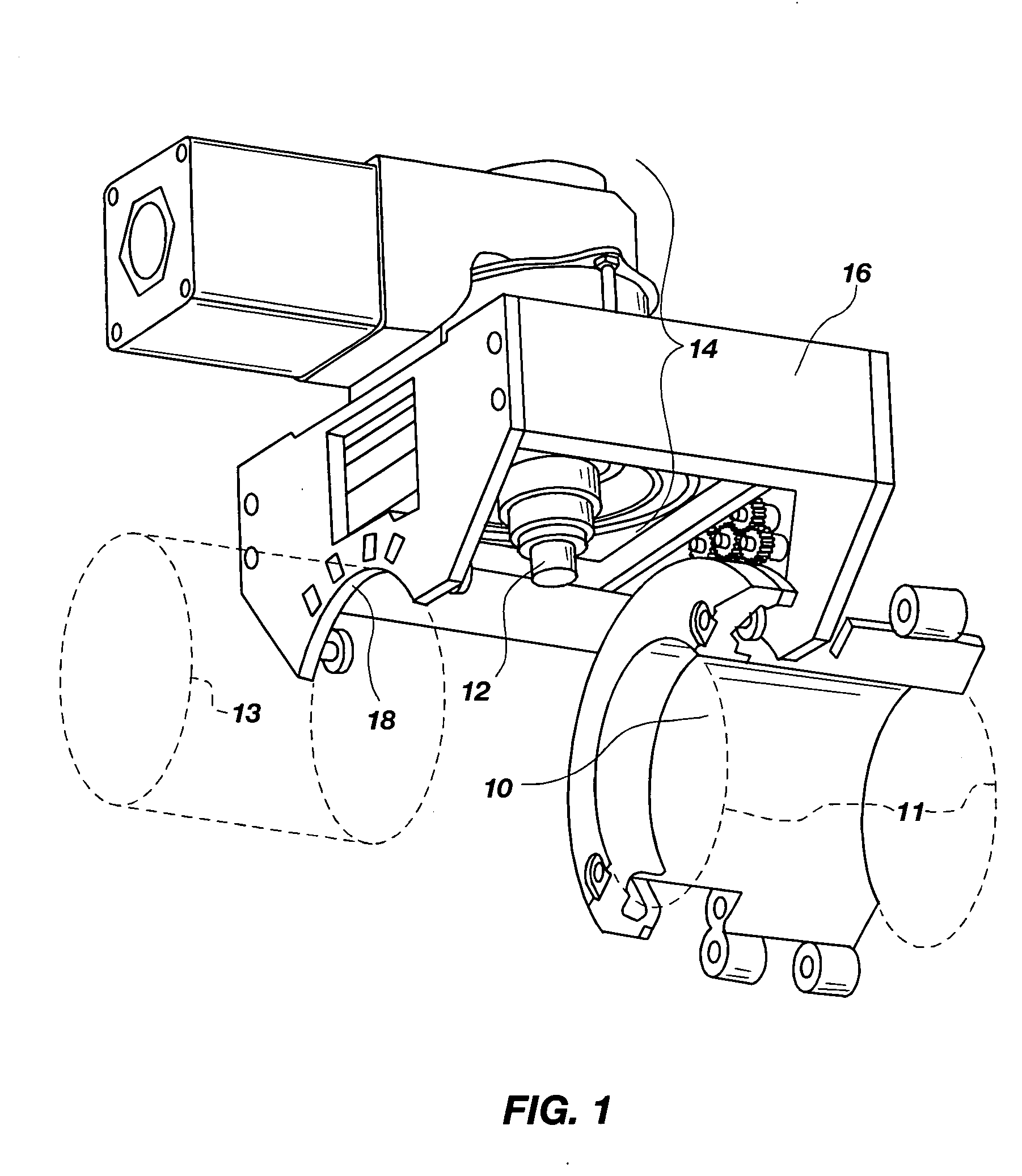
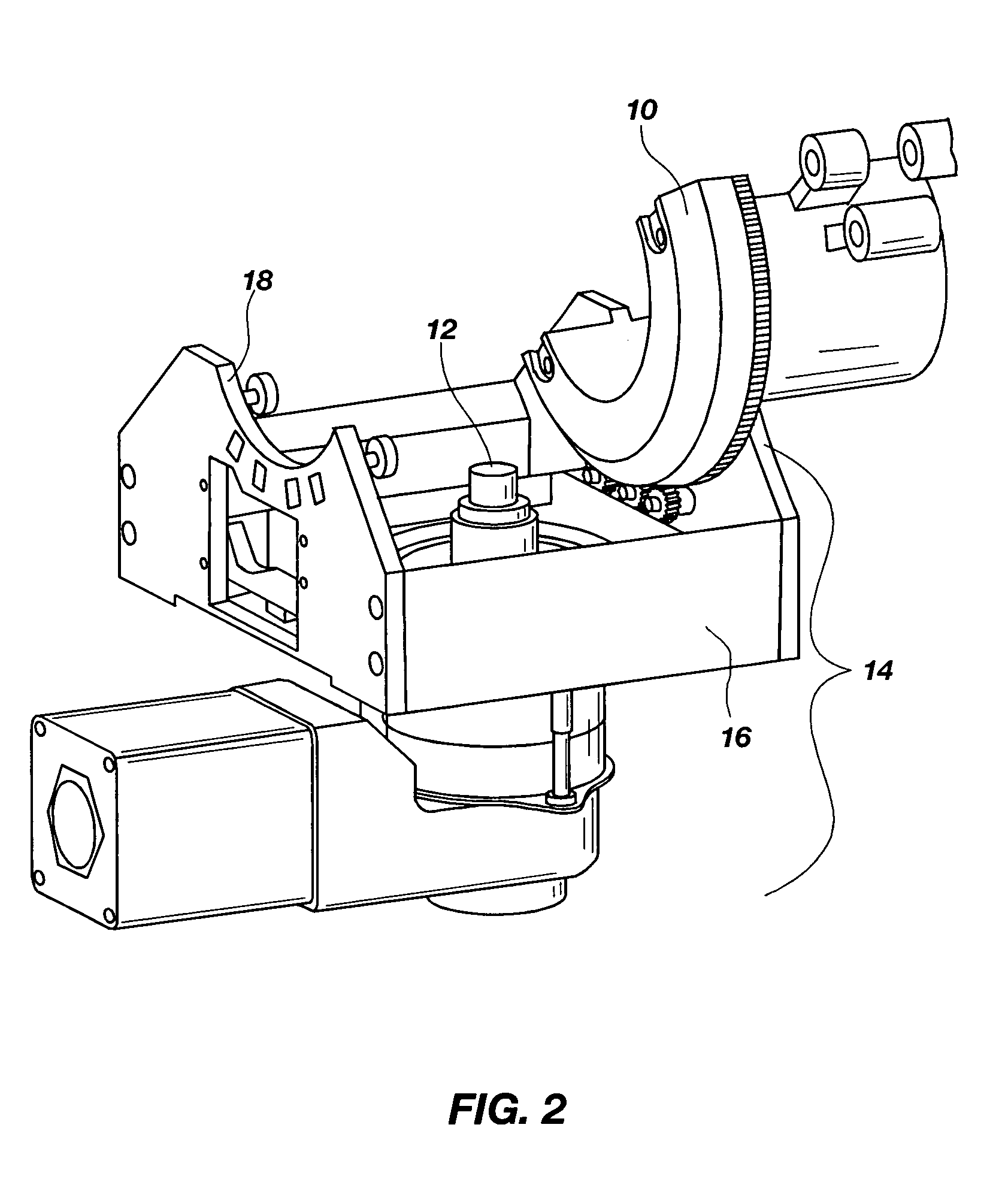
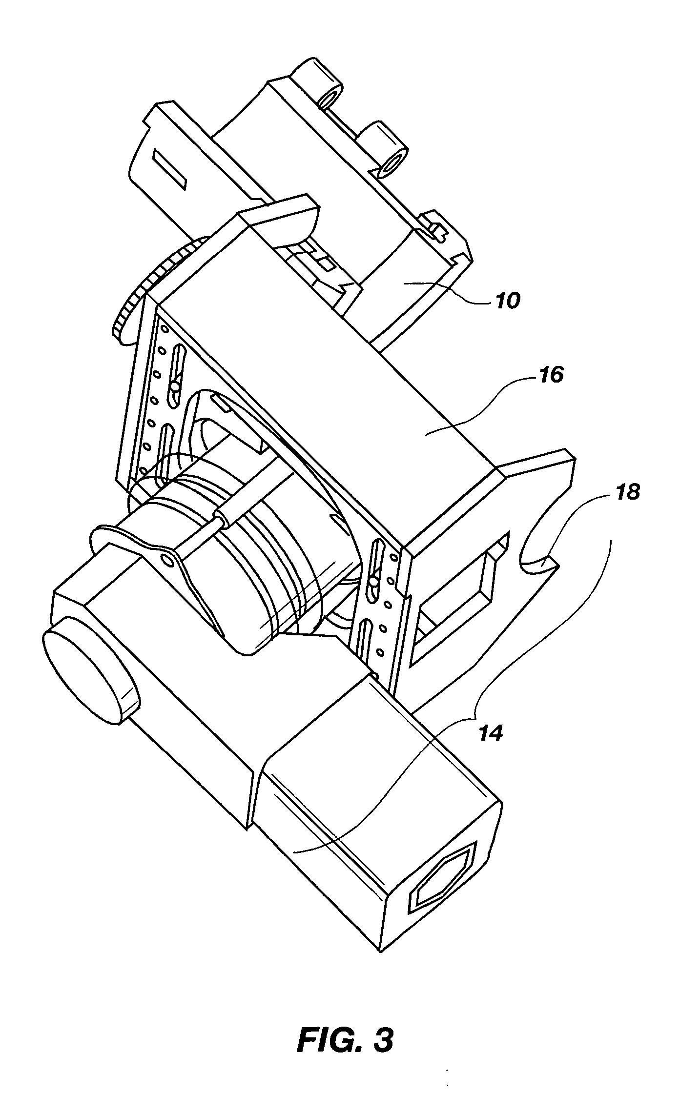
[0045] A first embodiment of the invention is a friction stir welding and clamping system that utilizes a first friction stir welding tool including a spindle head disposed so as to weld the OD of a pipe. FIG. 1 shows a partial clamp 10, and the tool 12 being held by the spindle head 14. An opposing clamping member not shown but its beginning and ending positions indicated by dotted lines 11 would hold a first pipe in place between the two clamps 10, 11. Two other clamping members also not shown by indicated by dotted lines 13 would be mounted on the frame 16 at location 18 to hold a seco...


PUM

PropertyMeasurementUnit
melting temperatureaaaaaaaaaa
microstructure propertiesaaaaaaaaaa
hardness propertiesaaaaaaaaaa

Abstract

A friction stir welding system that enables clamping of a pipe to enable friction stir welding around the pipe OD, a movable mandrel that provides a counter-force to the pressure exerted on the outside of a pipe by a tool, and a system for providing friction stir welding and repair inside a nuclear vessel in an underwater environment.

Description

CROSS REFERENCE TO RELATED APPLICATIONS [0001] This document incorporates by reference all of the subject matter filed in U.S. Pat. Ser. No. 6,648,206, in U.S. Pat. Ser. No. 6,779,704, and in U.S. patent application Ser. Nos. 10 / 846,825, and 10 / 912,736.BACKGROUND OF THE INVENTION [0002] 1. Field of the Invention [0003] This invention relates generally to friction stir welding. More specifically, the present invention addresses improvements in all aspects of friction stir welding of stainless steel and other materials that are harder than aluminum, wherein the improvements are focused on composite tools, control systems for friction stir welding machines, the use of fluids that can affect friction stir welding performance, modification of the hardness of friction stir welds, friction stir welding of pipe, the use of electric currents to affect the quality of friction stir welds, a mandrel for use in friction stir welding in pipes, improvements in friction stir welding of pipe, altern...

Claims


Application Information

Patent Timeline
Patent Type & Authority Applications(United States)
IPC IPC(8): B23KB23K20/12B23K20/227B23K37/053F16L55/26
CPCB23K20/1225B23K20/126B23K20/129B23K20/227F16L55/26B23K2201/04B23K2201/06B23K2203/04B23K37/0531B23K2101/04B23K2101/06B23K2103/05
Inventor BABB, JONATHAN A.TAYLOR, BRIAN E.STEEL, RUSSELL J.REED, CHRISPACKER, SCOTT M.
Owner MAZAK CORP
Learn More