Method of joining using reactive multilayer foils with enhanced control of molten joining materials

a multi-layer foil and enhanced control technology, applied in the direction of non-electric welding apparatus, process and machine control, explosions, etc., can solve the problems of reducing exposing both the components and the joint area to deleterious heat, and reducing the efficiency of annealing, etc., to achieve the effect of reducing equipment and processing costs, increasing the volume of melting material and/or the duration of melting

Inactive Publication Date: 2005-04-21
THE JOHN HOPKINS UNIV SCHOOL OF MEDICINE
View PDF24 Cites 58 Cited by
  • Summary
  • Abstract
  • Description
  • Claims
  • Application Information

AI Technical Summary

Benefits of technology

[0010] The present inventors have determined that, in the joining of bodies of material by reactive multilayer foils, there exists a critical applied pressure that will provide near maximal joint strength as compared to the strength produced by substantially higher pressures. Moreover they have further discovered that, within limits, the critical applied pressures can be reduced by increasing the volume of melting material and / or the duration of the melting.
[0011] Thus in accordance with the invention, bodies of materials are joined by disposing between them a reactive multilayer foil and one or more layers of meltable joining material such as braze or solder. The bodies are pressed together against the foil and joining material, and the foil is ignited to melt the joining material. The pressing is near the critical pressure and typically produces a joint having a strength of at least 70-85% the maximum strength producible at practical maximum pressures. Thus for example, reactively formed stainless steel soldered joints that were heretofore made at an applied pressure of about 100 MPa can be made with substantially the same strength at a critical applied pressure of about 10 kPa. Advantages of the process include minimization of braze or solder extrusion and reduced equipment and processing costs, especially in the joining of large bodies.

Problems solved by technology

Unfortunately, these conventional approaches often expose both the components and the joint areas to deleterious heat.
In brazing or soldering, temperature-sensitive components can be damaged, and thermal damage to the joint may necessitate costly and time consuming anneals.
Large coefficient of thermal expansion mismatches (CTE mismatches) can cause delamination or other damage.
While this process works well and can minimize deleterious heating of the bodies, it has been observed in some applications that molten joining material escapes laterally through the joint leaving a joining layer that is undesirably thin upon cooling and an undesirable external residue of joining material.
It has also been noted that the pressures usually used in this process (up to 100 MPa) present difficulties when very large components need to be joined.
Loading large components with high pressures is difficult and requires large, expensive equipment.

Method used


Image

  • Method of joining using reactive multilayer foils with enhanced control of molten joining materials
  • Method of joining using reactive multilayer foils with enhanced control of molten joining materials
  • Method of joining using reactive multilayer foils with enhanced control of molten joining materials

Examples


Embodiment Construction

[0037] This description is divided into two parts. Part I describes and illustrates reactive foil joining, and Part II describes control of molten joining material in the joining process. References indicated by bracketed numbers are fully cited in an attached list.

I. Joining of Bodies Using Reactive Multilayer Foil

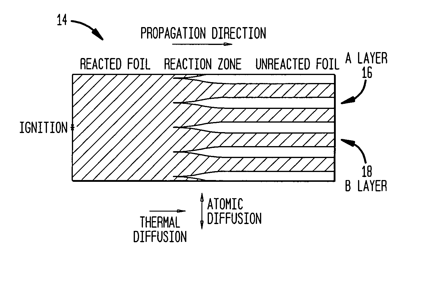
[0038] Self-propagating exothermic formation reactions have been observed in a variety of nanostructured multilayer foils, such as Al / Ni, Al / Ti, Ni / Si and Nb / Si foils [1-4] These reactions are driven by a reduction in atomic bond energy. Once the reactions are initiated by a pulse of energy, such as a small spark or a flame, atomic diffusion occurs normal to the layering.

[0039]FIG. 1 schematically illustrates a multilayer reactive foil 14 made up of alternating layers 16 and 18 of materials A and B, respectively. These alternating layers 16 and 18 may be any materials amenable to mixing of neighboring atoms (or having changes in chemical bonding) in response to a stim...


PUM

PropertyMeasurementUnit
pressureaaaaaaaaaa
pressureaaaaaaaaaa
thicknessaaaaaaaaaa

Abstract

In accordance with the invention, bodies of materials are joined by disposing between them a reactive multilayer foil and one or more layers of meltable joining material such as braze or solder. The bodies are pressed together against the foil and joining material, and the foil is ignited to melt the joining material. The pressing is near the critical pressure and typically produces a joint having a strength of at least 70-85% the maximum strength producible at practical maximum pressures. Thus for example, reactively formed stainless steel soldered joints that were heretofore made at an applied pressure of about 100 MPa can be made with substantially the same strength at a critical applied pressure of about 10 kPa. Advantages of the process include minimization of braze or solder extrusion and reduced equipment and processing costs, especially in the joining of large bodies.

Description

CROSS REFERENCE TO RELATED APPLICATIONS [0001] This application claims the benefit of U.S. Provisional Application Ser. No. 60 / 489,378 filed by Jiaping Wang et al. on Jul. 23, 2003 (entitled “Methodology of Controlling Flow of Molten Solder or Braze in Reactive Multilayer Joining”). [0002] This application is also a continuation-in-part of U.S. patent application Ser. No. 10 / 844,816 filed by Jiaping Wang et al. on May 13, 2004 (entitled “Nanostructured Soldered or Brazed Joints Made With Reactive Multilayered Foils”) which, in turn, claims the benefit of two United States Provisional Applications: 1) Ser. No. 60 / 469,841 filed by Etienne Besnoir et al. on May 13, 2003 (entitled “Method of Controlling Thermal Waves In Reactive Multilayer Joining and Resulting Product”), and 2) Ser. No. 60 / 475,830 filed by Jiaping Wang et al. on Jun. 4, 2003 (entitled “Microstructure of Solder or Braze in Joints Made With Freestanding Reactive Multilayer Foils”). [0003] This application is also a conti...

Claims


Application Information

Patent Timeline
Patent Type & Authority Applications(United States)
IPC IPC(8): B23K1/00B23K20/00B23K20/06B23K20/08B23K28/00B23K31/02B23K31/12B23K35/02B23K35/34B32B15/01C06B21/00C06B45/14C23C14/14F24V30/00G05B17/02H05K3/34
CPCB23K1/0006Y10T428/12632B23K20/00B23K20/06B23K20/08B23K20/165B23K28/00B23K31/02B23K31/12B23K35/0233B23K35/0238B23K35/34B23K2201/40B23K2203/04B23K2203/10B32B15/01B32B15/017C06B21/0083C06B45/14C23C14/14F24J1/00G05B17/02H05K3/3463H05K3/3494H05K2203/0405H05K2203/1163B23K1/0016F24V30/00B23K2101/40B23K2103/05B23K2103/10
Inventor WANG, JIAPINGKNIO, OMARWEIHS, TIMOTHY P.
Owner THE JOHN HOPKINS UNIV SCHOOL OF MEDICINE
Why Eureka
Try Eureka