
Preform for producing an optical fiber and method therefor

a technology of fiberoptic preforms and fiberoptic fibers, which is applied in the direction of cladding optical fibres, manufacturing tools, instruments, etc., can solve the problems of difficult to deliver known and stable concentrations of dopant precursor species, difficult process control, and limited technique for implementing optical fiber designs having any but the most rudimentary characteristics, etc., to achieve high-controlled and controllable compositions, physical, chemical, optical properties, and the effect of high controllable composition

Inactive Publication Date: 2005-04-21
NAT TECH & ENG SOLUTIONS OF SANDIA LLC
View PDF11 Cites 4 Cited by
  • Summary
  • Abstract
  • Description
  • Claims
  • Application Information

AI Technical Summary

Benefits of technology

This approach allows for the production of optical fibers with highly controlled physical, chemical, and optical properties, overcoming the limitations of traditional methods by decoupling core and cladding indices and reducing thermal decomposition effects, resulting in improved performance and versatility in fiber designs.

Problems solved by technology

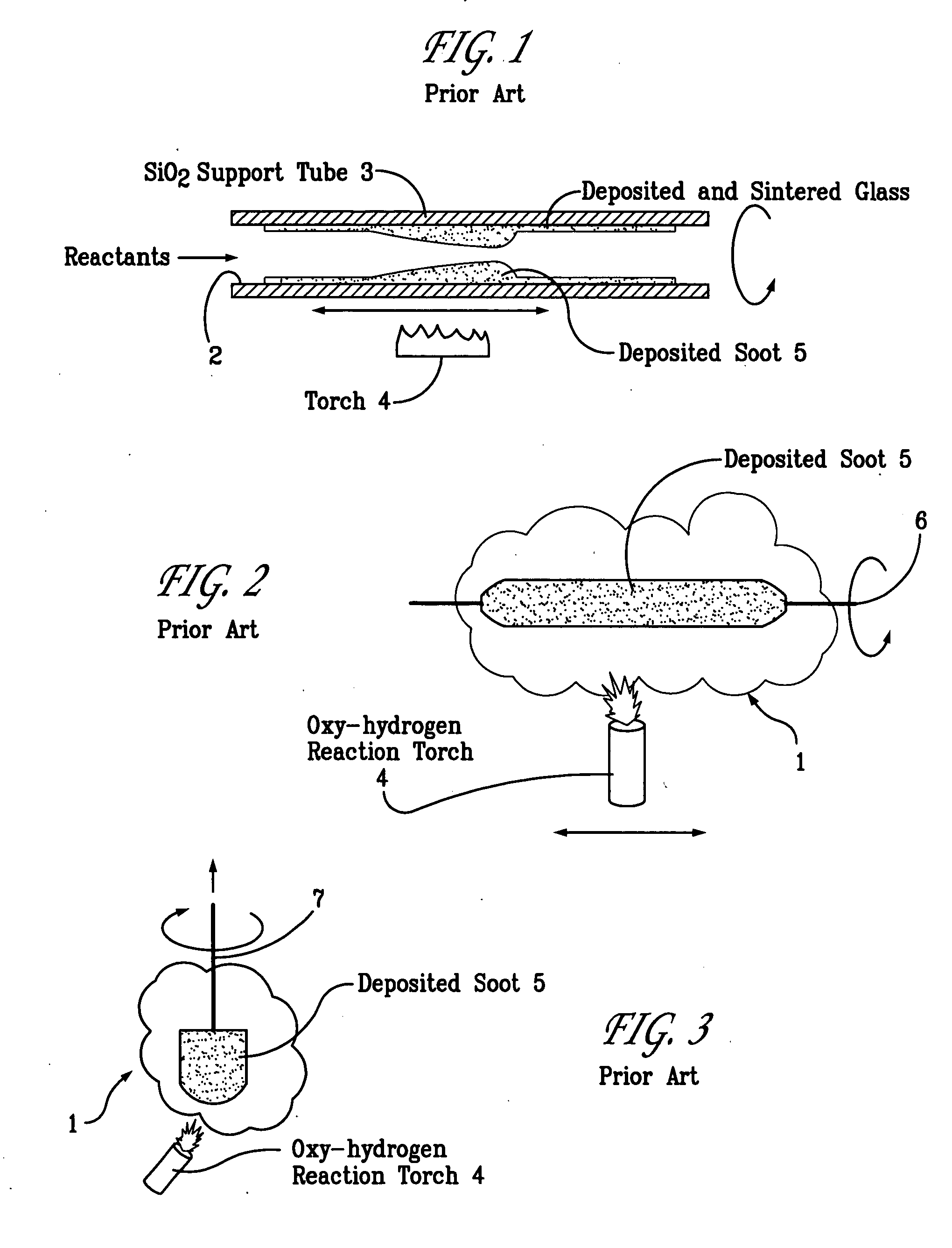
However, while simple this technique was also quite limited in its ability to implement optical fiber designs having any but the most rudimentary characteristics, and newer methods capable of producing ultra-low-loss fibers, such as are required for optical telecommunications, have essentially replaced the rod-in-tube technique.
A characteristic common to all vapor-deposition techniques is poor process control.
Delivering known and stable concentrations of dopant precursor species is particularly difficult.
In addition, these species are very reactive, making it difficult to use mass-flow controllers or similar devices to regulate reactant flow rates and therefore rates of species addition.
Similarly, with the solution doping technique, the distribution of dopant species incorporated into the host material is often non-uniform and unpredictable (the density and pore size of the partially sintered glass network can vary substantially).
As a result, the range of fiber designs that can be fabricated is quite limited.
This limitation persists despite large investments of time and resources in the development of optical fibers for a wide variety of commercially significant applications {see S. E. Miller and A. G. Chynoweth eds., Optical Fiber Telecommunications (Academic Press, San Diego, Calif., 1979); P. C. Becker, N. A. Olsson, and J. R. Simpson, Erbium-Doped Fiber Amplifiers (Academic Press, San Diego, Calif., 1999)}.

Method used


Image

  • Preform for producing an optical fiber and method therefor
  • Preform for producing an optical fiber and method therefor
  • Preform for producing an optical fiber and method therefor

Examples


Embodiment Construction

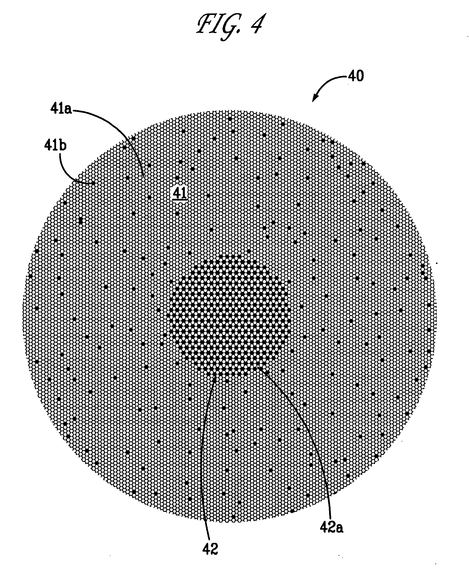
[0041]FIG. 4 is exemplary of the present invention, wherein preform 40 is fabricated from a large number of glass rods bundled together and then fused at high temperature. FIG. 4 shows such a preform, looking down the axis of the preform, prior to fusion. The preform shown in this example is for a rare-earth-doped fiber with a stepped refractive index core 42 of uniform dopant density (a “step-index” profile).

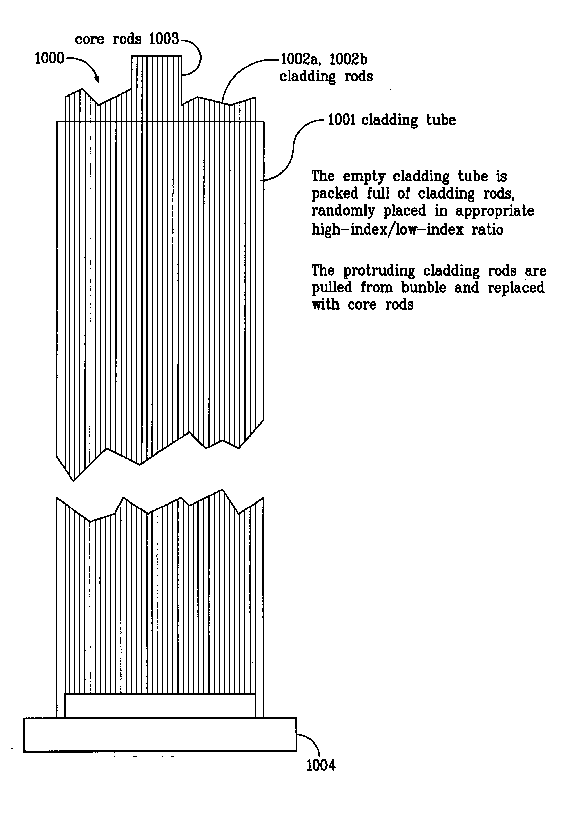
[0042] Core region 42 of the preform contains rods 42a fabricated from rare-earth-doped glass with a refractive index of ncore. Cladding region 41 of the preform contains two different types of glass rods, 41a and 41b, neither of which contains rare-earth dopants. One type of cladding rod has a refractive index slightly greater than the desired cladding refractive index, nclad. The other type of cladding rod has a refractive index slightly less than clad. The ratio of low-index / high-index cladding rods is chosen so that the average index of refraction in the cladding region is...


PUM

PropertyMeasurementUnit
temperatureaaaaaaaaaa
thickaaaaaaaaaa

Abstract

The present invention provides a simple method for fabricating fiber-optic glass preforms having complex refractive index configurations and / or dopant distributions in a radial direction with a high degree of accuracy and precision. The method teaches bundling together a plurality of glass rods of specific physical, chemical, or optical properties and wherein the rod bundle is fused in a manner that maintains the cross-sectional composition and refractive-index profiles established by the position of the rods.

Description

[0001] The United States Government has rights in this invention pursuant to Contract No. DE-AC04-94AL85000 between the United States Department of Energy and Sandia Corporation for the operation of Sandia National Laboratories.BACKGROUND OF THE INVENTION [0002] The present invention is a method for fabricating fiber-optic preforms with complex refractive-index and / or dopant distributions to a high degree of accuracy and precision. In particular, the present invention focuses on the fabrication of performs for providing rare-earth-doped optical fibers such as those widely used in fiber amplifiers and lasers. [0003] The simplest method of preform fabrication is the so-called “rod-in-tube” method such as is disclosed and described in Pat. Nos. 4,668,263 and 4,264,347. A rod of glass that will form the core of the fiber is inserted into a thick-walled tube that will become the cladding, and the two are fused together at high temperature. The relative dimensions of the core and cladding...

Claims


Application Information

Patent Timeline
Patent Type & Authority Applications(United States)
IPC IPC(8): C03B19/10C03B37/012C03B37/027G02B6/02
CPCC03B19/106C03B37/01217C03B37/0122C03B37/01225C03B37/01274H01S3/06716C03B37/0279C03B2201/31C03B2201/34C03B2203/30C03B2203/42C03B37/01297
Inventor KLINER, DAHV A. V.KOPLOW, JEFFERY P.
Owner NAT TECH & ENG SOLUTIONS OF SANDIA LLC
Learn More