This helps you quickly interpret patents by identifying the three key elements:
Problems solved by technology
Method used
Benefits of technology
Benefits of technology
[0012] In accordance with the above construction, since the gap between the gasket and the gas diffusion electrode is partially closed, the cell reaction gases which are not exposed to the gas diffusion electrodes decrease. Consequently, utilization ratio of the gases increases.
[0017] In accordance with such a construction, since the elastic body fitted in the inner surface of the electrically conductive separator serves to position the MEA-gasket assembly and the electrically conductive separator, assembly of the MEA-gasket assembly and the electrically conductive separator is facilitated and done well.
[0020] In accordance such a construction, since water remains in and closes the gap between the gasket and the gas diffusion electrode, the cell reaction gases which are not exposed to the gas diffusion electrode decrease, and consequently, the utilization ratio of the gases increases. In addition, since a large amount of water remains in the gap and thereby the polymer electrolyte membrane contains water in re-start of the polymer electrolyte fuel cell, the time required from start to a rated operation in re-start of the fuel cell becomes shorter than the time required in a first start.
Problems solved by technology
The presence of cell reaction gases which are not exposed to the gas diffusion electrodes 107 reduces the utilization ratio of these gases and hence reduces power generation efficiency.
In addition, since the gaskets are made from a material such as liquid EPDM or rubber which is highly elastic and highly durable with respect to temperature variation or reactive materials, the manufacturing cost of the fuel cell substantially increases.
Method used
Image
Click on the blue label to locate the original text in one second.
Reading with bidirectional positioning of images and text.
Examples
embodiment 1
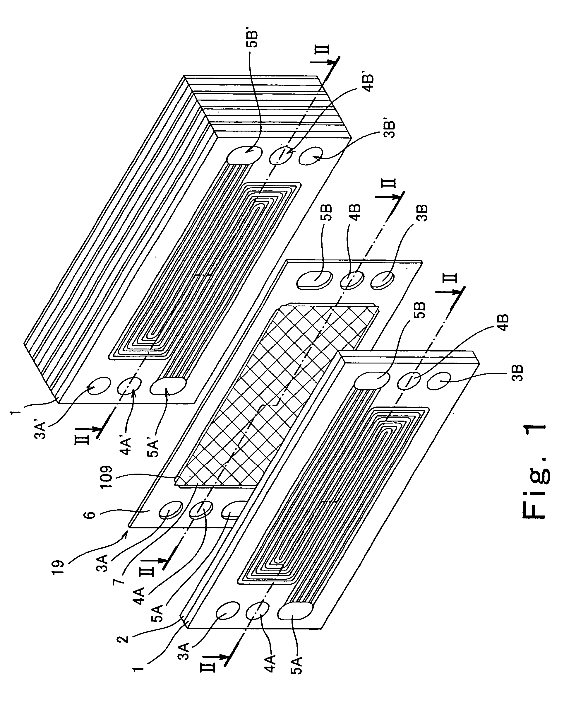
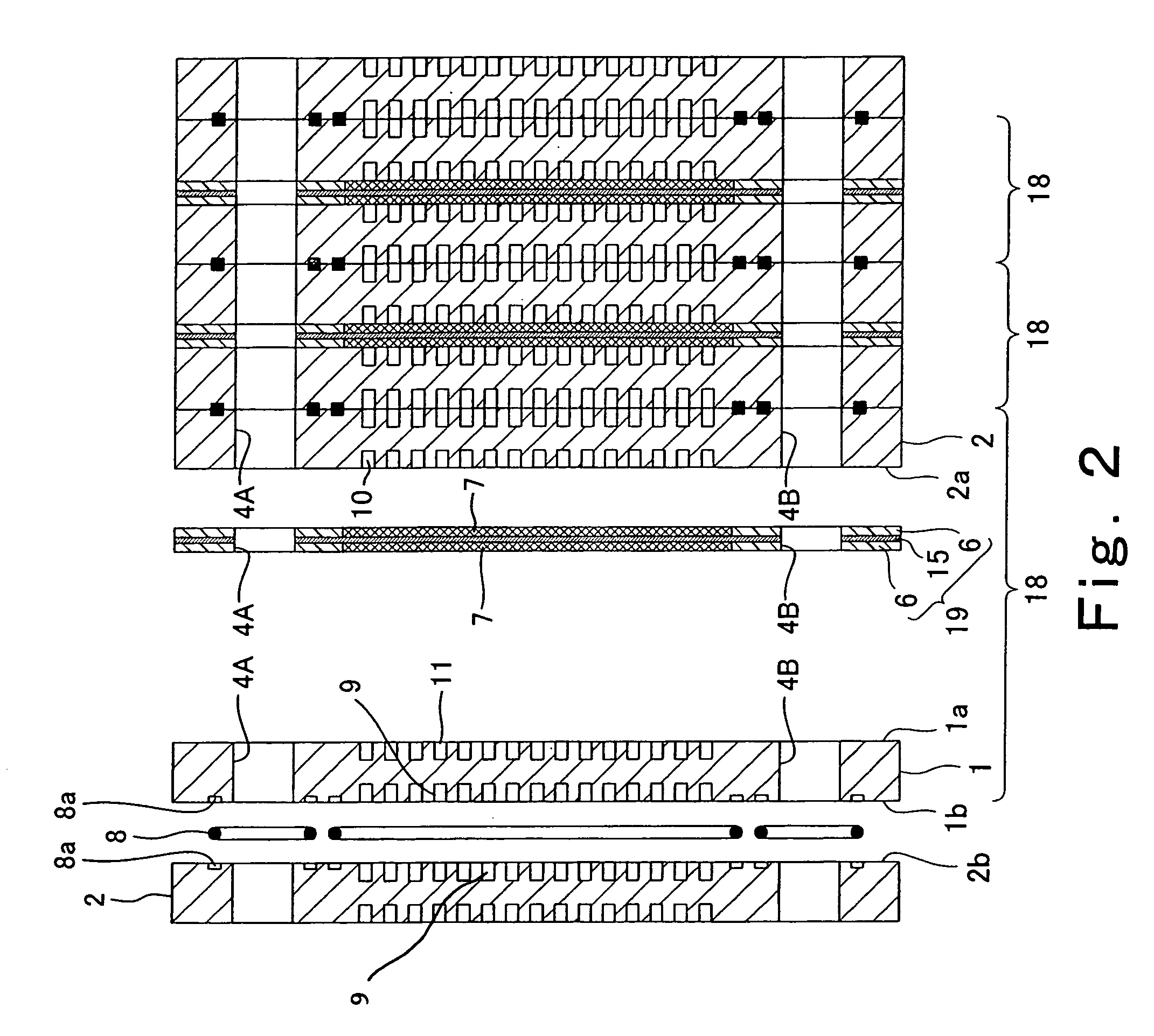
[0048]FIG. 1 is a exploded perspective view showing the structure of a polymer electrolyte fuel cell according to a first embodiment of the present invention. In FIG. 1, a stack structure of the polymer electrolyte fuel cell is partially exploded for the sake of convenience. FIG. 2 is a cross-sectional view taken along line II-II in FIG. 1. As in the structure of FIG. 1, a stack structure of the polymer electrolyte fuel cell is exploded for the sake of convenience.
[0049] Referring now to FIGS. 1 and 2, the polymer electrolyte fuel cell is formed by stacked cells 18 (unit cells: see FIG. 2).
[0050] As shown in FIG. 2, the cell 18 is structured such that an MEA (membrane electrode assembly)-gasket assembly 19 is sandwiched between a cathode-side electrically conductive separator (hereinafter referred to as a cathode separator) 1 and an anode-side electrically conductive separator (hereinafter referred to as an anode separator) 2.
[0051] As shown in FIG. 1, a pair of a fuel gas supply...
example 1
[0064] In this example according to Embodiment 1 the MEA-gasket assembly 19 in FIGS. 5 and 6 was manufactured by the following process.
[0065] First, platinum was carried in a weight ration of 1:1 on KETJEN® BLACK EC (furnace black produced by Ketjen Black International Co., Ltd) with a specific surface area of 800 m2 / g and a DBP oil absorbing amount of 360 ml / 100 g. Then, 35 g of water and 59 g of a liquid alcohol dispersion of hydrogenionconductive polymer electrolyte (9% FSS produced by Asahi Garasu Co. Ltd) were mixed with 10 g of catalyst powder, and were dispersed by ultrasonic agitator, thereby producing a catalyst layer ink. The catalyst layer ink was applied to polypropylene film (TREFAN® 50-2500 produced by Toray Co. Ltd) and dried, thereby forming the catalyst layers 13 and 14. The catalyst layers 13 and 14 were cut into pieces of 104×216 mm, which were transferred to center portions of surfaces on both sides of the polymer electrolyte membrane 12 of 330×150 mm (50 μm t...
embodiment 2
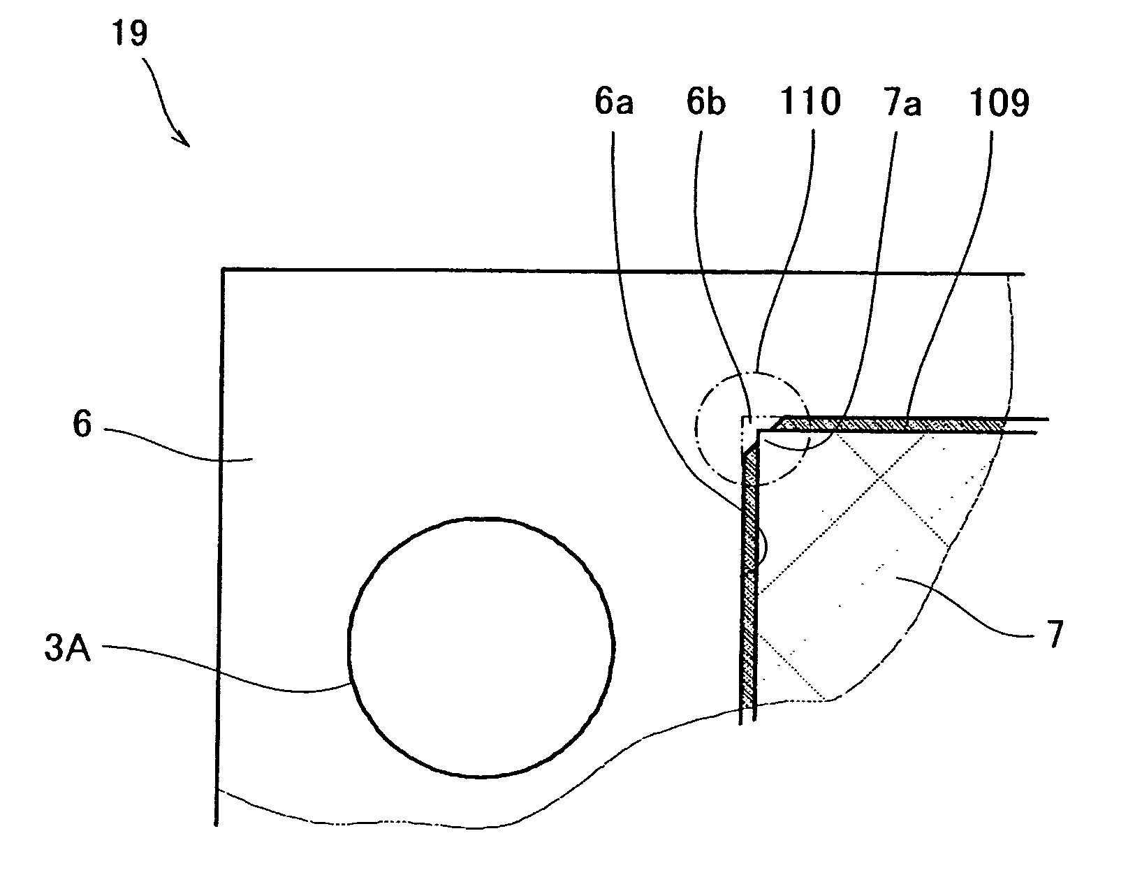
[0073]FIG. 9 is a plan view showing the structure of an MEA-gasket assembly 19 of a polymer electrolyte fuel cell according to a second embodiment of the present invention. FIG. 10A is an enlarged plan view showing the structure of the portion represented by X in FIG. 9. In FIGS. 9 and 10A, the same reference numerals as those in FIGS. 5 and 6 denote the same or corresponding parts.
[0074] Referring to FIGS. 9 and 10A, the MEA-gasket assembly 19 of the second embodiment is substantially identical to that of the MEA-gasket assembly 19 of the first embodiment except for the structure of the gap 109 between the gasket 6 and the gas diffusion electrode 7.
[0075] As shown in FIGS. 9 and 10A, in the MEA-gasket assembly 19, the gap 109 between the gasket 6 and the gas diffusion electrode 7 is formed in the shape of rectangular wave (6 mm pitch×50 turn). More specifically, the outer periphery of the gas diffusion electrode 7 is formed in convex and concave shapes composed of a continuous se...
PUM
Abstract
A polymerelectrolyte fuel cell has an MEA-gasketassembly including an MEA having a polymerelectrolyte membrane, a pair of catalyst layers, and a pair of gas diffusion electrodes, and a pair of gaskets provided on peripheral portions of surfaces on both sides of the MEA with gaps between the respectively adjacent gaskets and gas diffusion electrodes. A pair of electrically conductive separators is disposed to sandwich the MEA-gasketassembly with groove-shaped cell reaction gas passages on inner surfaces of the separators, each of the cell reaction gas passages running sequentially across a first portion of a respective gasket of the pair of gaskets, a first portion of a respective gap of the gaps, a respective gas diffusion electrode of the pair of gas diffusion electrodes, a second portion of the respective gap, and a second portion of the respective gasket. Each of the gaps is at least partially closed by a closure.
Description
BACKGROUND OF THE INVENTION [0001] The present invention relates to the structure of a polymerelectrolyte fuel cell. More particularly, the present invention relates to a stack assembly structure of a membrane electrode assembly (MEA), gaskets, and electrically conductive separators. [0002] The conventional polymer electrolyte fuel cell has a basic power generation element as described below (see Japanese Patent No. 3045316). FIG. 21 is a plan view showing the structure of an assembly comprising a polymer electrolyte membrane electrode assembly which is the conventional basic power generation element and a gasket 106. The polymer electrolyte membrane electrode assembly is called an MEA (membrane electrode assembly). FIG. 22 is an enlarged plan view showing the structure of the portion represented by XXII in FIG. 21. FIG. 23 is a cross-sectional view taken along line XXIII-XXIII in FIG. 22. [0003] Referring to FIG. 23, an MEA 15 comprises a polymer electrolyte membrane 12 formed by ...
Claims
Application Information
Patent Timeline
Application Date:The date an application was filed.
Publication Date:The date a patent or application was officially published.
First Publication Date:The earliest publication date of a patent with the same application number.
Issue Date:Publication date of the patent grant document.
PCT Entry Date:The Entry date of PCT National Phase.
Estimated Expiry Date:The statutory expiry date of a patent right according to the Patent Law, and it is the longest term of protection that the patent right can achieve without the termination of the patent right due to other reasons(Term extension factor has been taken into account ).
Invalid Date:Actual expiry date is based on effective date or publication date of legal transaction data of invalid patent.

