Nitric acid regeneration fuel cell systems

a fuel cell and nitric acid technology, applied in the field of fuel cells, can solve the problems of not meeting the concomitant problems of existing fuel cell technology, fuel cell systems are not optimal for working within a closed recirculating microfluidic, and existing fuel cell technology has not addressed many of the concomitant problems

Active Publication Date: 2005-04-21
EPD INVESTMENT CO
View PDF28 Cites 37 Cited by
  • Summary
  • Abstract
  • Description
  • Claims
  • Application Information

AI Technical Summary

Problems solved by technology

Unfortunately, existing state-of-the-art fuel cell systems are not entirely satisfactory for the production of small-scale portable direct feed fuel cell systems, in part, because of problems associated with achieving a small form factor while maintaining a relatively high power density.
In addition, existing fuel cell technology has not addressed many of the concomitant problems associated with closed circulating microfluidic liquid feed fuel cell systems adapted for use with portable electronic devices.
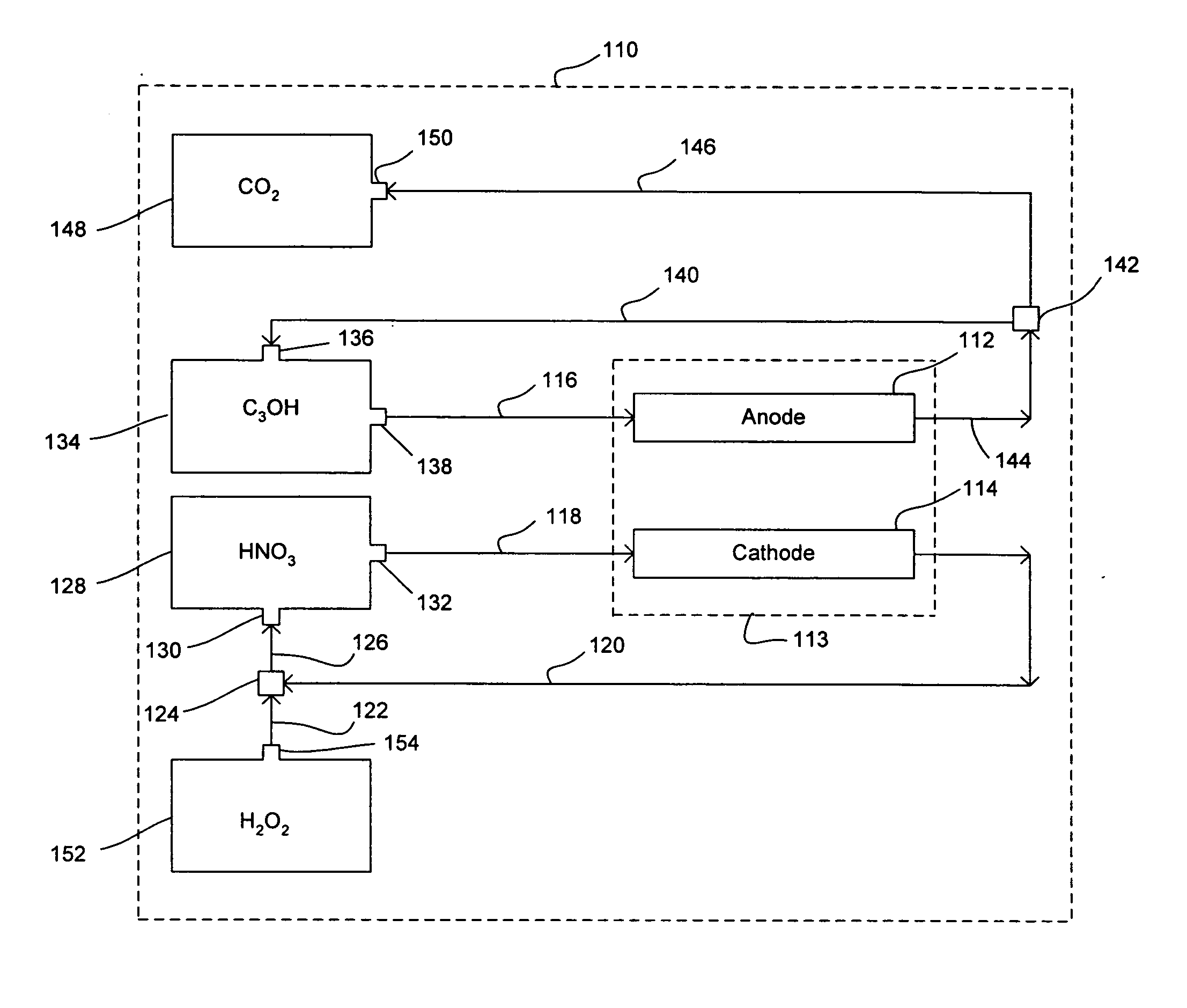
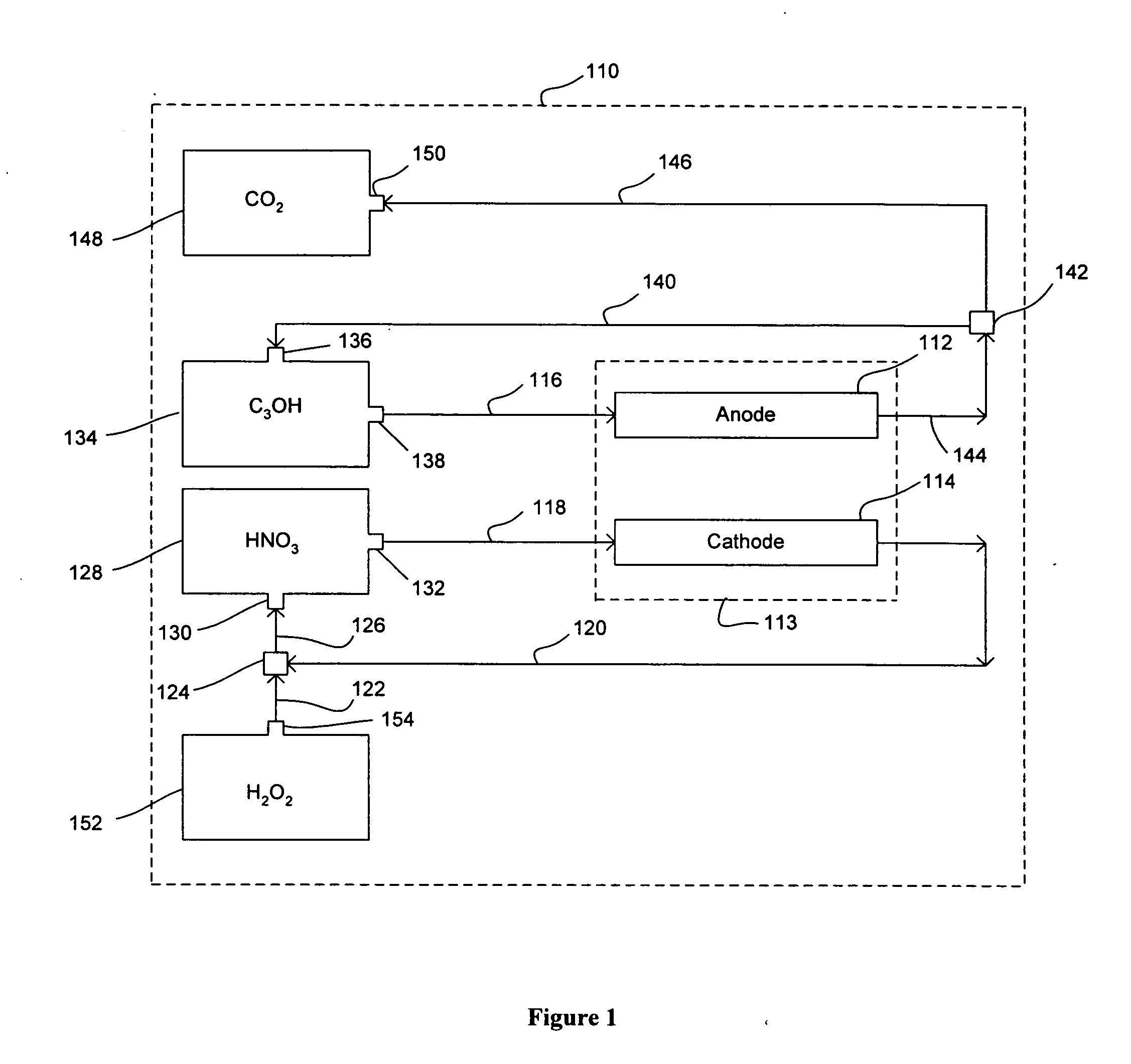
Most all of these systems, however, use a nitric acid catholyte flowstream that is regenerated with oxygen gas from the air; and as such, these fuel cell systems are not optimal for working within a closed recirculating microfluidic liquid feed fuel cell system adapted for use with a portable electronic device.

Method used


Image

  • Nitric acid regeneration fuel cell systems
  • Nitric acid regeneration fuel cell systems
  • Nitric acid regeneration fuel cell systems

Examples


example 1

Performance of Porous Silicon-Based Cathode Reacting with Nitric Acid Flowstream

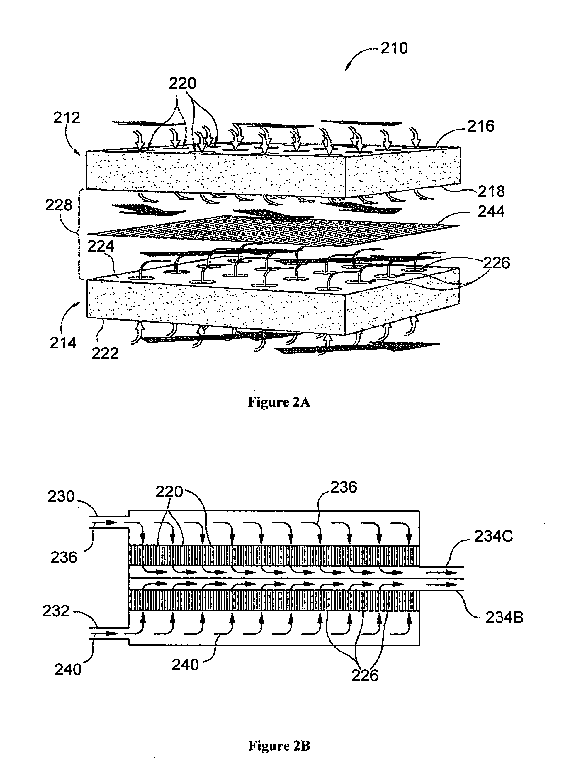
[0049] An investigation was conducted to determine the performance characteristics associated with a cathode half-cell made from a porous silicon-based substrate. For our investigation, a single 2 cm by 2 cm square coupon electrode having an 0.89 cm by 0.89 cm active porous hydrodynamic flow-through region was made by HF anodic etching of a silicon wafer etching. In this regard, an n-type silicon wafer having a resistively of 23-27 ohm-cm, a (100) crystal orientation, and a thickness of 525 μm was initially masked and etched with KOH to form an ordered array of etched pits (each pit of about 5 μm in diameter). The silicon substrate was then etched with 4 wt % HF—H2O solution with an additional 1 vol % (of the HF solution) surfactant (NCW-1001, Wako Chemicals, Inc., USA) at a current density of about 10 mA / cm2 at 14° C. A potential of 1.4 V (min) to 6 V (max) was applied with backside illumination at 880...

example 2

Regeneration with a Hydrogen Peroxide Flowstream

[0052] A further investigation was conducted in order to demonstrate the feasibility of regenerating catholyte effluent flowstreams produced in a manner similar to those of Example 1. More specifically, various concentrated hydrogen peroxide flowstreams were mixed together with various catholyte effluent flowstreams via small tubing at a reaction zone and it was repeatedly demonstrated that an approximate 78% conversion rate of NO back to HNO3 could be achieved.


PUM

PropertyMeasurementUnit
thicknessaaaaaaaaaa
flow rateaaaaaaaaaa
porosityaaaaaaaaaa

Abstract

The present invention disclosed herein is directed to nitric acid regeneration fuel cell systems that comprise: an anode; a cathode confronting and spaced apart from the anode; an anolyte flowstream configured to flowingly contact the anode, wherein the anolyte flowstream includes a fuel, preferably methanol, for reacting at the anode; a catholyte flowstream configured to flowingly contact the cathode, wherein the catholyte flowstream includes nitric acid for reacting at the cathode to thereby yield cathode reaction products that include nitric oxide and water in a catholyte effluent flowstream; and a hydrogen peroxide flowstream configured to contact and react hydrogen peroxide with the nitric oxide of the catholyte effluent flowstream at a hydrogen peroxide oxidation zone to thereby yield a regenerated nitric acid flowstream. The regenerated nitric acid flowstream is preferably reused in the catholyte flowstream.

Description

CROSS-REFERENCE TO RELATED APPLICATION [0001] This application claims the benefit of U.S. Provisional Application No. 60 / 512,629 filed on Oct. 17, 2003, which application is incorporated herein by reference in its entirety for all purposes.GOVERNMENT RIGHTS [0002] This invention was made with United States Government support under Advanced Technology Program Award Number 70NANB3H3036 awarded by the National Institute of Standards and Technology (NIST). The United States Government has certain rights in this invention.TECHNICAL FIELD [0003] The present invention relates generally to fuel cells and, more particularly, to nitric acid regeneration fuel cell systems having a recirculating nitric acid catholyte flowstream that is regenerated with a hydrogen peroxide flowstream, as well as to related methods. BACKGROUND OF THE INVENTION [0004] A fuel cell is an energy conversion device that consists essentially of two opposing electrodes, an anode and a cathode, ionically connected togethe...

Claims


Application Information

Patent Timeline
Patent Type & Authority Applications(United States)
IPC IPC(8): H01MH01M2/14H01M8/04H01M8/08H01M8/18H01M8/20
CPCH01M8/04007H01M8/04291Y02E60/528H01M8/18H01M8/20H01M8/1011H01M8/04164H01M8/0668Y02E60/50
Inventor OHLSEN, LEROY J.PETROVIC, SLOBODANWINE, DAVID W.ROY, LORNEBIRASHK, JULIE
Owner EPD INVESTMENT CO
Why Eureka
Try Eureka