Systems and methods for selective cell and/or stack control in a flowing electrolyte battery

a technology of selective cell and/or stack control, applied in the direction of cell components, process and machine control, instruments, etc., can solve the problems of power users, costing the industry as much as $400 billion a year in power disturbances, and millions of dollars in loss for businesses, so as to increase the flexibility of cell stacks, and reduce the risk of uneven cell plating

Active Publication Date: 2005-04-21
LARGO CLEAN ENERGY CORP
View PDF56 Cites 71 Cited by
  • Summary
  • Abstract
  • Description
  • Claims
  • Application Information

AI Technical Summary

Benefits of technology

[0013] The invention addresses the deficiencies in the prior art by providing, in various embodiments, improved, methods, systems and features for controlling, monitoring, charging and / or discharging (collectively “controlling”) flowing electrolyte batteries. According to one aspect, the invention addresses the deficiencies in the prior art by providing methods, systems and features for controlling individual stacks of battery cells in a flowing electrolyte battery. In a further embodiment, the invention provides methods, systems and features for controlling individual battery cells in a flowing electrolyte battery. Among other advantages, the invention increases the flexibility with which cell stacks can be charged and stripped; enables regular and ongoing battery maintenance, without taking the battery offline; maintains the battery at a predictable and consistent charge capacity; reduces the likelihood of stack failures due, for example, to electrolyte flow blockage, thermal runaway, and / or dendrite formation; reduces the risk of uneven cell plating; increases the number of charge / discharge cycles available; and reduces expenses relating to maintaining redundant battery systems.

Problems solved by technology

Blackouts and other power inconsistencies present a problem for power users.
Even seconds of downtime or minor aberrations in power quality can translate into millions of dollars of loss for businesses.
The Electric Power Research Institute (EPRI) has estimated that power disturbances cost industry as much as $400 billion a year.
The public utility grid was not designed, nor is it equipped to deliver power without interruption.
It also lacks the ability to modulate, condition and improve the power it delivers—increasing the risk that customers will be subjected to surges, sags and other power quality inconsistencies.
Furthermore, the more than 2.5 million miles of electric wire that deliver power from the country's main grids are vulnerable to all types of risk.
Severe weather can cause major outages, but even the occasional downed wire or broken pole can threaten to shut down production, leave workers idle, and / or stop communications.
Existing alternatives, however, still leave companies with no fully satisfactory distributed generation system.
All of these options, however, require local energy storage to work effectively.
Solar and wind power are energy sources of opportunity, meaning they are not always available all day every day.
These technologies, however, do not load follow.
Moreover, differences in the open circuit voltages between stacks are typically indicative of some internal abnormality that has lowered a stack's internal resistance.
Additionally, nucleation on the electrodes can cause dendrite formation and branching between cells.
Differences in open-circuit voltages between stacks in flowing electrolyte battery systems can affect the charge and discharge cycles of the stacks and, potentially, the operation of the battery.
Moreover, the additional zinc stored in the faulty stack typically comes from the electrolyte normally utilized by neighboring stacks.
Another consequence is that the stack having the increased zinc accumulation does not fully strip during discharge; eventually resulting in zinc accumulating on the electrodes of the faulty stack to such an extent that it causes internal short circuiting between the cells of the stack.
This can potentially destroy the stack and possibly, the entire battery.
As the electrolyte flow acts to cool the stack, the restricted flow may cause the stack to over heat and melt critical components.
However, a full strip of a flowing electrolyte battery is typically time consuming (often taking one or two days to complete) and may have to be repeated every few days for a recurring problem.
A full strip of the battery typically renders it unavailable or at a significantly reduced capacity for electrical applications, necessitating the purchase and installation of additional redundant battery systems.
Moreover, a full strip is often unnecessary since typically a minority of the stacks in the battery is operating abnormally.

Method used


Image

  • Systems and methods for selective cell and/or stack control in a flowing electrolyte battery
  • Systems and methods for selective cell and/or stack control in a flowing electrolyte battery
  • Systems and methods for selective cell and/or stack control in a flowing electrolyte battery

Examples


Embodiment Construction

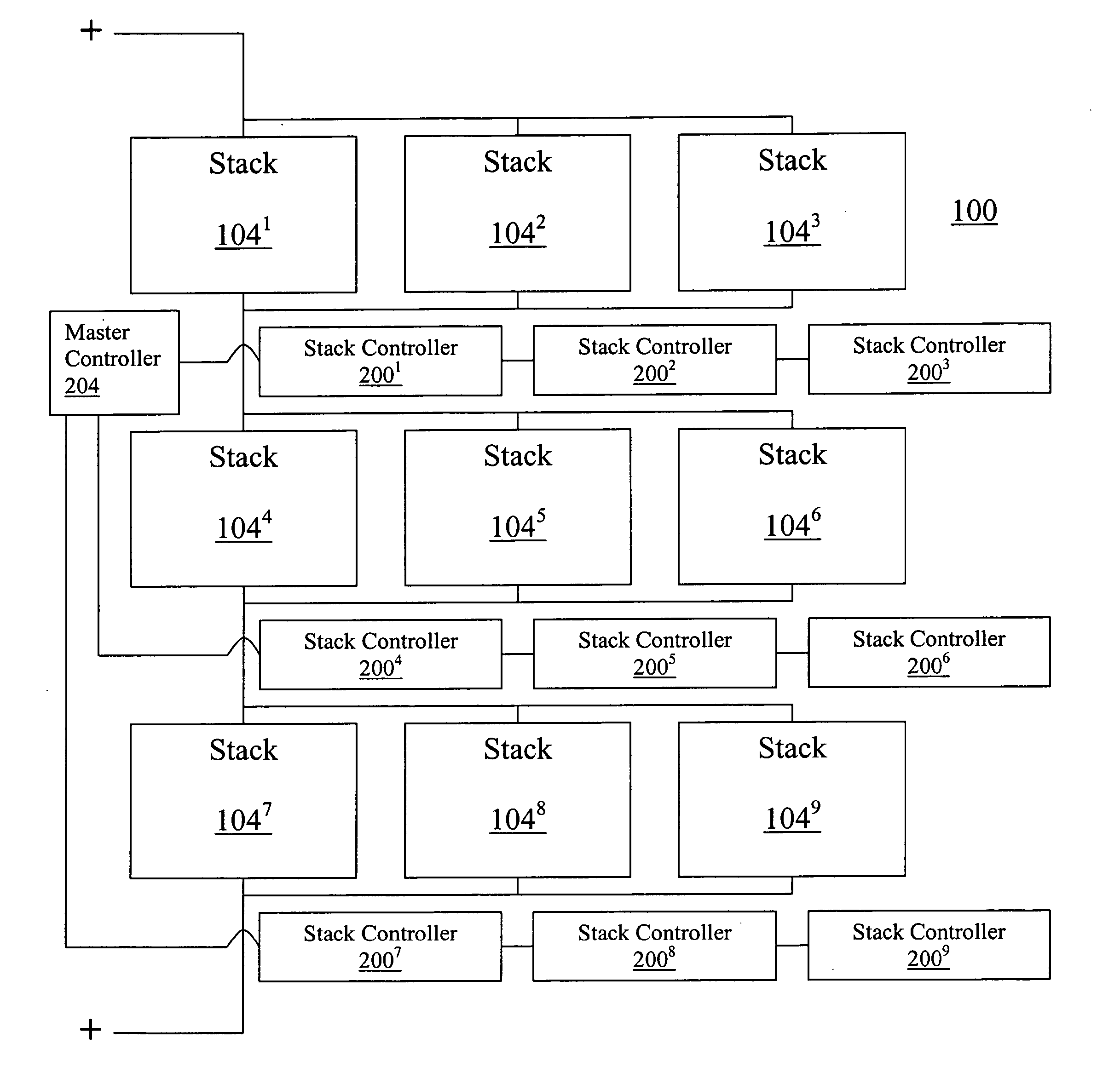
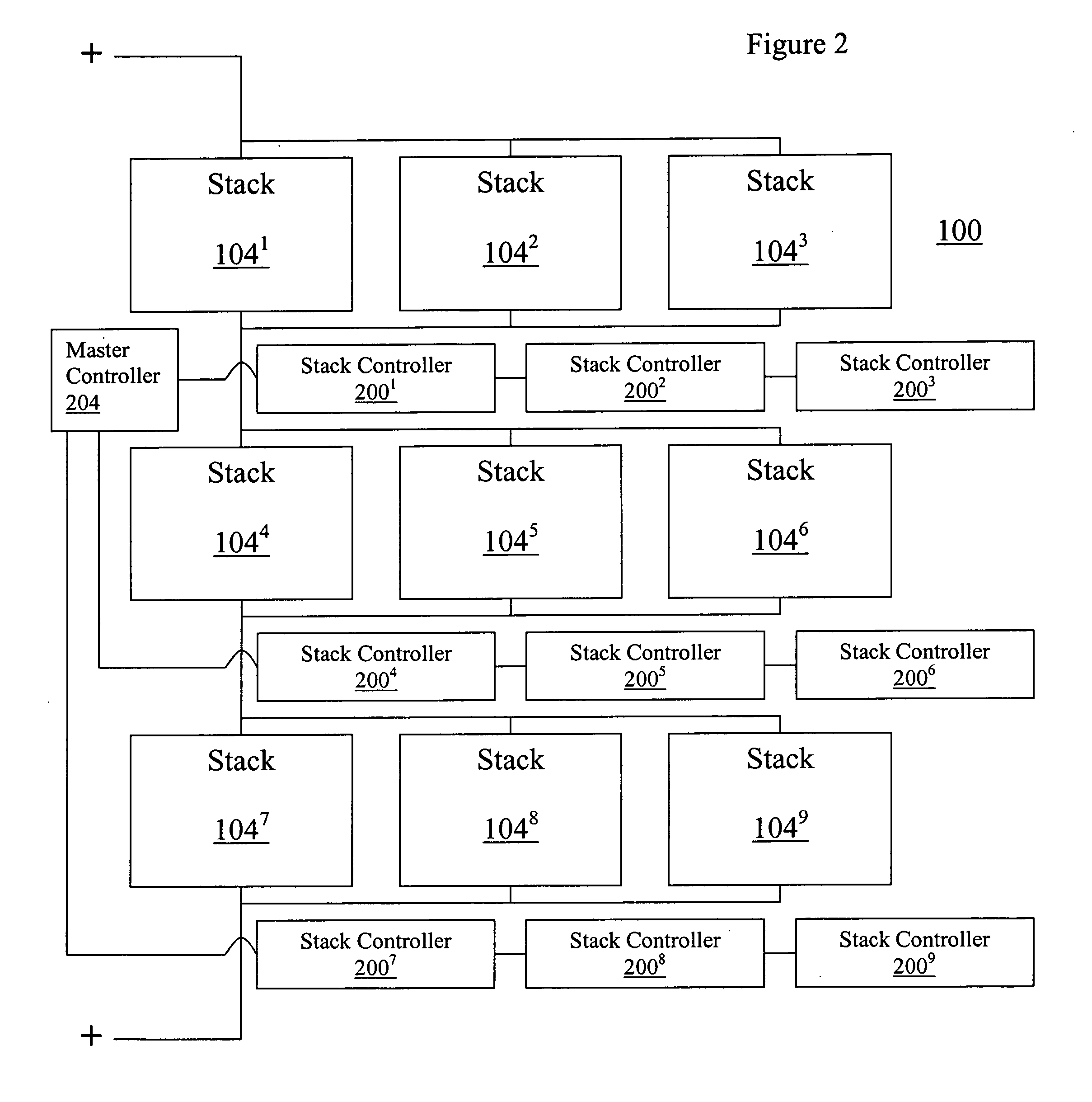
[0044] As discussed above in summary, the invention addresses the deficiencies in the prior art by providing, in various embodiments, improved, methods, systems and features for controlling, monitoring, charging and / or discharging (collectively “controlling”) flowing electrolyte batteries. According to some illustrative embodiments, the invention addresses the deficiencies in the prior art by providing methods, systems and features for controlling individual stacks of battery cells in a flowing electrolyte battery. In other illustrative embodiments, the invention provides methods, systems and features for controlling individual battery cells in a flowing electrolyte battery. In other illustrative embodiments, stack controllers and sensors interconnected with individual battery stacks and / or cells provide detection of a fault conditions, and in response to detecting such fault conditions, alter one or more charging conditions of individual battery stacks and / or cells. If necessary, a...


PUM

PropertyMeasurementUnit
timeaaaaaaaaaa
charging currentaaaaaaaaaa

Abstract

The invention provides in various embodiments methods and systems relating to controlling energy storage units in flowing electrolyte batteries.

Description

CROSS-REFERENCE TO RELATED APPLICATIONS [0001] This application is related to and claims the benefit of pending U.S. Provisional Patent Application No. 60 / 485,871, filed on Jul. 9, 2003, and entitled “Features, Controls and Methods Relating to a Flowing Electrolyte Battery and a Uninterruptible Power Source Employing a Flowing Electrolyte Battery” the entire contents of which are incorporated herein by reference.FIELD OF THE INVENTION [0002] The invention relates generally to operation of flowing electrolyte batteries. In particular, in one aspect, the invention relates to methods and systems for controlling, monitoring, charging, and / or discharging (collectively “controlling”) flowing electrolyte batteries. BACKGROUND OF THE INVENTION [0003] Blackouts and other power inconsistencies present a problem for power users. Even seconds of downtime or minor aberrations in power quality can translate into millions of dollars of loss for businesses. The Electric Power Research Institute (EP...

Claims


Application Information

Patent Timeline
Patent Type & Authority Applications(United States)
IPC IPC(8): G01R31/36
CPCG01R31/362G01R31/3624H01M8/04679G01R31/3662G01R31/3675G01R31/3658G01R31/374G01R31/3835G01R31/3842G01R31/389G01R31/396Y02E60/50
Inventor COLELLO, GARY M.DARCY, DENNIS M.
Owner LARGO CLEAN ENERGY CORP
Why Eureka
Try Eureka