Method and apparatus for patterning a workpiece

a workpiece and patterning technology, applied in the field of lithography methods and methods, can solve the problems of high cost, double the capital and operating cost of the pattern generator per produced workpiece, and many cases be economically impossibl

Active Publication Date: 2005-04-21
ASML NETHERLANDS BV
View PDF19 Cites 57 Cited by
  • Summary
  • Abstract
  • Description
  • Claims
  • Application Information

AI Technical Summary

Benefits of technology

[0057] Another aspect of the present invention is to provide an imp

Problems solved by technology

Different rasterizing multipass schemes can be devised, but it is a problem to find schemes that simultaneously give improvements in all six aspects mentioned above.
It is in a general sense possible to make pattern fidelity better by increasing the number of passes, but the cost is high.
Doubling the number of passes doubles the capital and operating cost of the pattern generator per produced workpiece and can in many cases be economically impossible.

Method used


Image

  • Method and apparatus for patterning a workpiece
  • Method and apparatus for patterning a workpiece
  • Method and apparatus for patterning a workpiece

Examples


Embodiment Construction

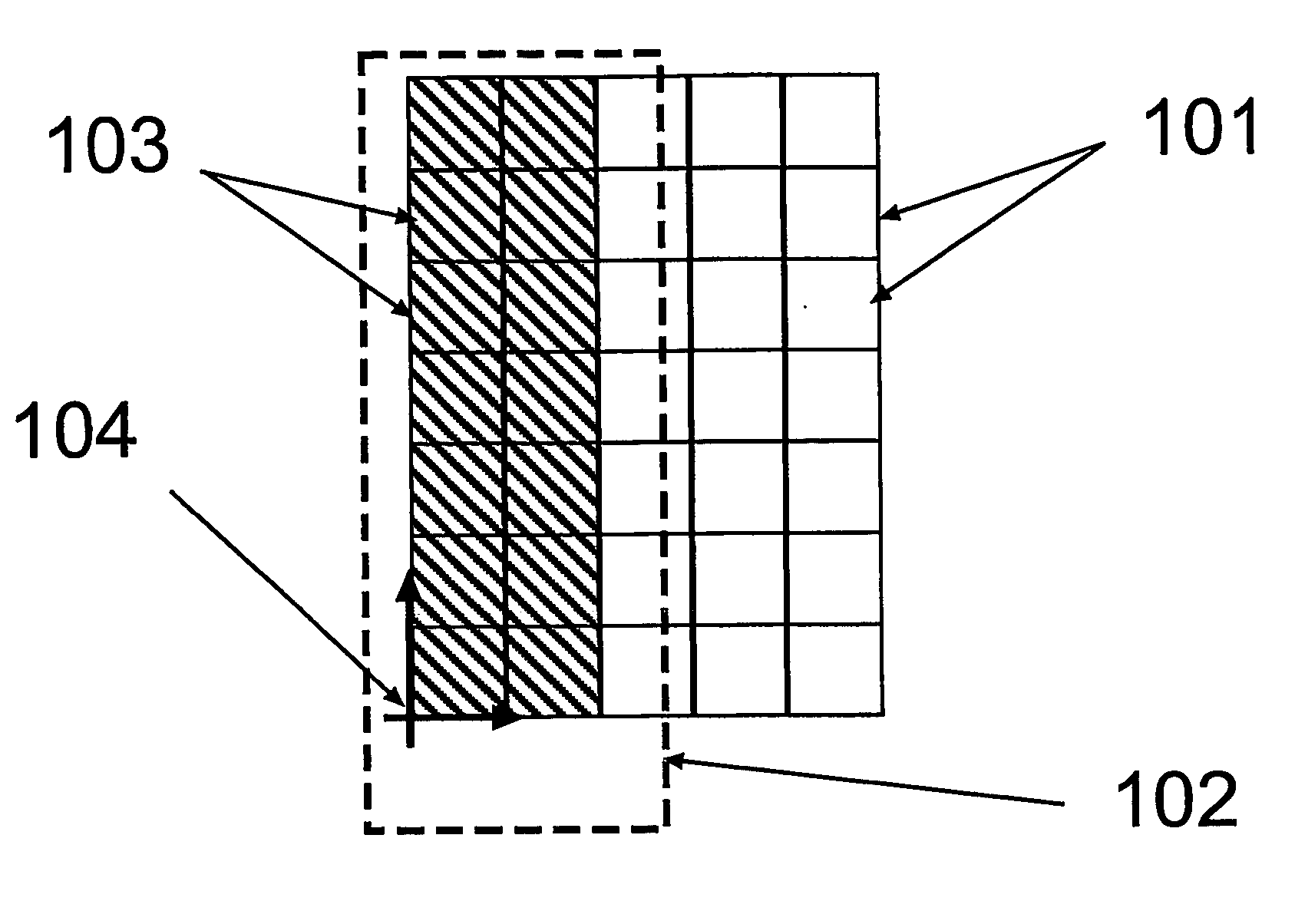
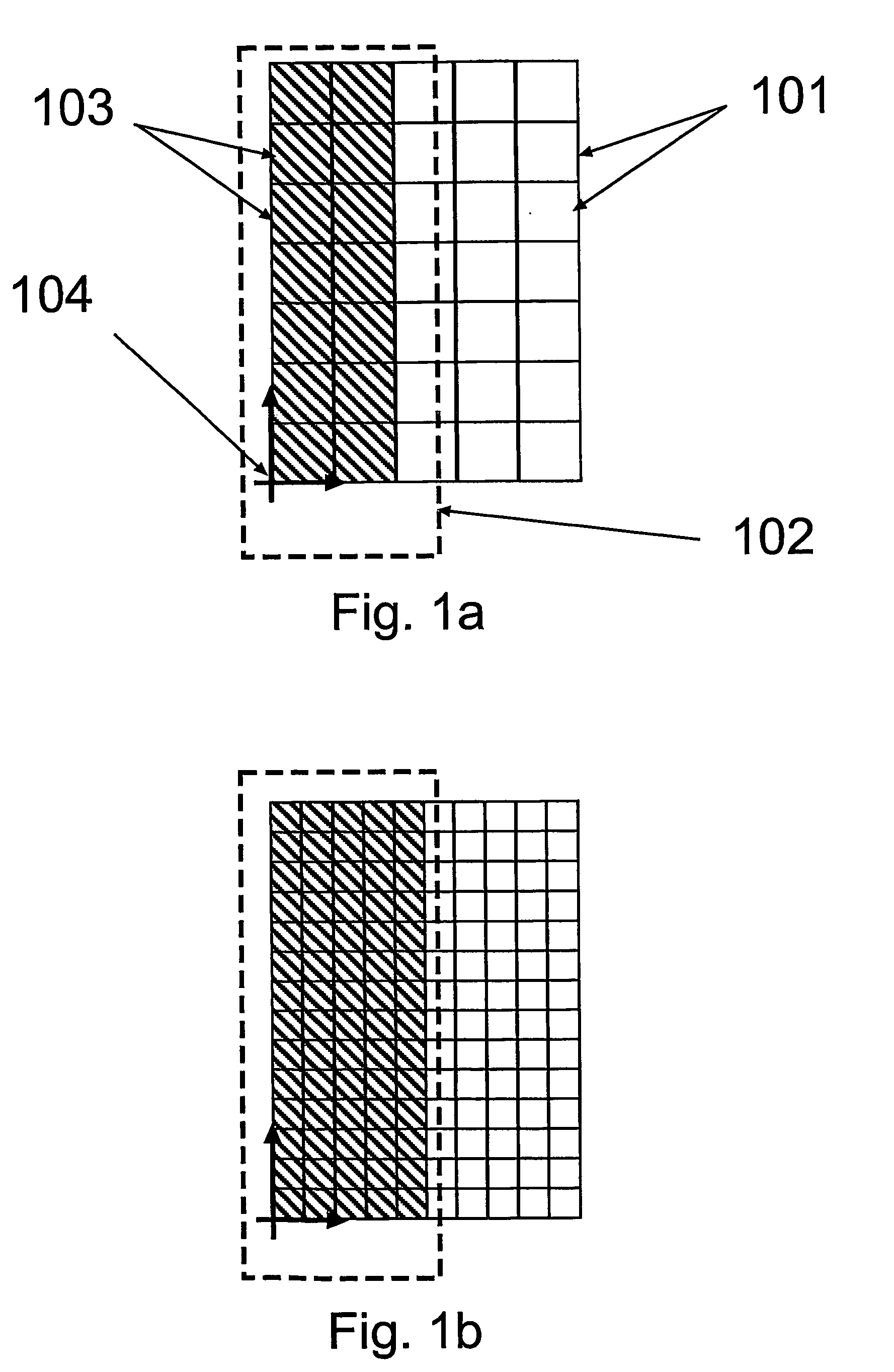
[0132]FIG. 1a illustrates a rasterized feature 102. A grid 101 comprising pixels 103 is aligned to an origin 104 of a coordinate system. From FIG. 1a one can see that the grid is somewhat to coarse Therefore the feature 102 may not be imaged as accurate as desired.

[0133]FIG. 1b illustrates the same feature as shown in FIG. 1a, but here the feature is rasterized to a finer grid. The accuracy of the rasterizing is two times better, but there are four time more pixels to write, which may make this method more time consuming relative the one illustrated in FIG. 1a.

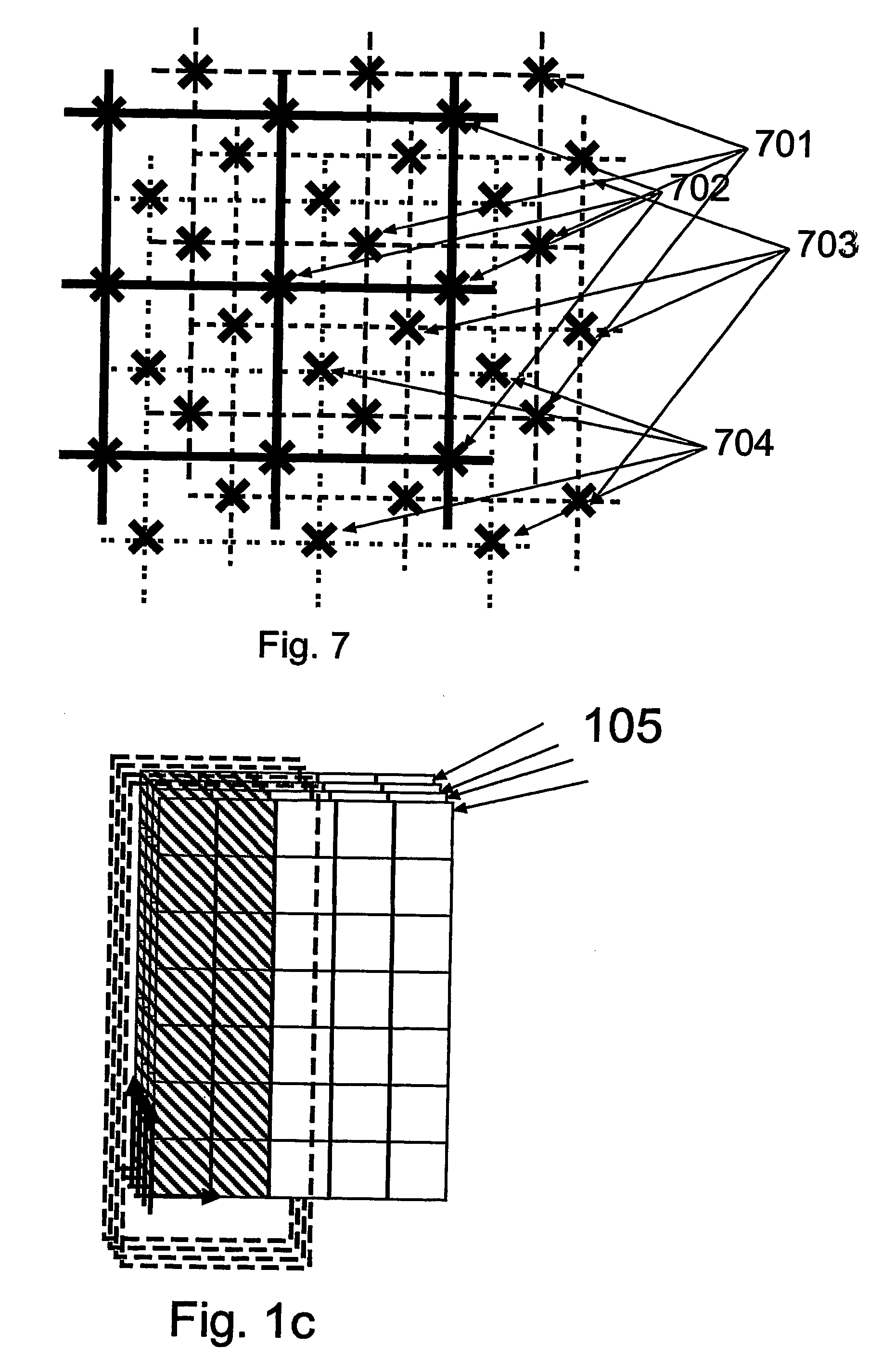
[0134]FIG. 1c illustrates the same feature as shown in FIG. 1a rasterized to the same grid size but using four passes 105 with no offset. Different lithographical characteristics such as resist properties and time delays may make this method of imaging more accurate than the one illustrated in FIG. 1a given that the different passes are imaged with equal doses.

[0135]FIG. 2a illustrates a rasterized vertical line. FIG. 2b il...


PUM


Abstract

The present invention relates to a method for creating a pattern on a workpiece sensitive to electromagnetic radiation. Electromagnetic radiation is emitted onto a computer controlled reticle having a multitude of modulating elements (pixels). The pixels are arranged in said computer controlled reticle according to a digital description. An image of said computer controlled reticle is created on said workpiece, wherein said pixels in said computer controlled reticle are arranged in alternate states along at least a part of one feature edge in order to create a smaller address grid. The invention also relates to an apparatus for creating a pattern on a workpiece. The invention also relates to a semiconducting wafer and a mask.

Description

TECHNICAL FIELD [0001] The present invention relates in general to techniques to obtain improved images. In particular it relates methods of lithography using a computer controlled imaging arrangement, such as for instance a Spatial Light Modulator (SLM), with an improved virtual grid. It also relates to an apparatus for patterning a work piece comprising such a method. DESCRIPTION OF THE BACKGROUND ART [0002] Lithographic production is useful for integrated circuits, masks, reticles, flat panel displays, micro-mechanical or micro-optical devices and packaging devices, e.g. lead frames and MCM's. Lithographic production may involve an optical system to image a master pattern from a computer-controlled reticle onto a workpiece. A suitable workpiece may comprise a layer sensitive to electromagnetic radiation, for example visible or non-visible light. An example of such a system is described in WO 9945435 with the same inventor and applicant as the present invention. [0003] Said comput...

Claims


Application Information

Patent Timeline
IPC IPC(8): G03F7/20H01L21/02H01L21/027G03F1/68H04N1/036H04N1/04H04N1/17
CPCG03F7/2057G03F7/70283G03F7/70441G03F7/70433G03F7/70291G03F7/70508
Inventor SANDSTROM, TORBJORN
Owner ASML NETHERLANDS BV
Why Eureka
Try Eureka