Ink-jet printer head and a manufacturing method thereof

a technology of printer head and manufacturing method, which is applied in the direction of liquid surface applicators, coatings, printing, etc., can solve the problems of requiring maintenance or cleaning of the nozzle surface, affecting the dimensions and dimensional accuracy of the jetted ink droplets, and inviting “discharge failures”

Inactive Publication Date: 2005-04-28
RICOH KK
View PDF9 Cites 24 Cited by
  • Summary
  • Abstract
  • Description
  • Claims
  • Application Information

AI Technical Summary

Benefits of technology

[0008] Accordingly, an object of the present invention is to provide a technique for protecting a resinous film having C-F bonds from damage during cleaning of nozzles, which resinous film having C-F bonds exhibits ink repellency but has low mechanical strength.
[0009] To protect hydrophobic molecules on an ink-repellent layer from a cleaning jig during cleaning of the nozzle surface, the present invention employs an ink-repellent film containing solid particles which are dispersed in a resinous film and protrude from a surface of the resinous film to a specific height so as to avoid the contact between the ink-repellent molecules and the cleaning jig geometrically.
[0012] The present invention proposes a technique for improving durability of an ink-repellent layer (film) arranged on a nozzle plate of an ink-jet head. The contact between a cleaning jig and ink-repellent molecules is geometrically avoided according to the present invention to protect the ink-repellent molecules on a surface having an ink-repellent property from the cleaning jig during cleaning of the nozzle surface. Specifically, one of the most important features of the present invention is that the ink-repellent film is so configured as to be a resin film having solid particles protruded from a surface of the resinous film to a specific height. According to this configuration, the fluorocarbon polymer which performs an ink-repellent function is neither worn nor damaged even during cleaning and can maintain its ink repellency over a long period of time. The object of maintaining the ink repellency over a long period of time is achieved by uniformly dispersing solid particles between the ink-repellent plane and the cleaning plane so as to enable the solid particles to serve as a spacer.
[0016] According to the present invention, the fluorocarbon polymer chains which perform an ink-repellent function are protected from wear (abrasion) and damage during cleaning, and the ink repellency of the fluorocarbon polymer chains can be maintained over a long period of time.

Problems solved by technology

In addition, the properties of a surface of a member forming the nozzle orifices, particularly of a surface around the nozzle orifices, significantly affect the dimensions and dimensional accuracy of the jetted ink droplets.
If ink is attached to the surface around the nozzle orifices to form a non-uniform ink pool, for example, the discharge direction of ink droplets may be deflected, and, at worst, a meniscus to be formed in the nozzle orifices may not be formed due to the ink pool, thus inviting “discharge failures”.
Even according to this technique, however, the nozzle surface requires maintenance or cleaning, since ink derived from, for example, mist of discharged ink pools on the nozzle surface.
Such a fluorine-containing material, however, has low mechanical strength and thereby wears during cleaning.
Thus, the fluorine-containing material inherently has low mechanical strength.
In other words, such a fluorocarbon resin as intact cannot play its role in a cleaning system in which the nozzle surface is firmly wiped to thereby remove unnecessary substances such as ink and dust.
The film, however, is supposed not to keep its ink-repellent property because the polyimide is damaged during cleaning.
Because of this, the water-repellent characteristics are excellent, but there was a problem for the endurance.

Method used


Image

  • Ink-jet printer head and a manufacturing method thereof
  • Ink-jet printer head and a manufacturing method thereof
  • Ink-jet printer head and a manufacturing method thereof

Examples


example 1

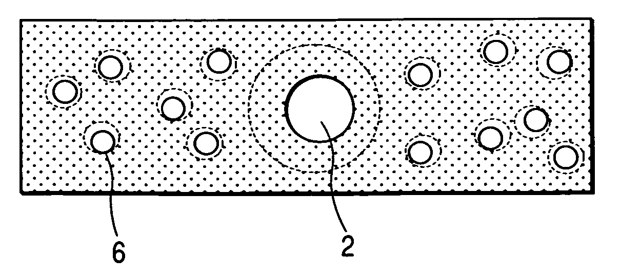
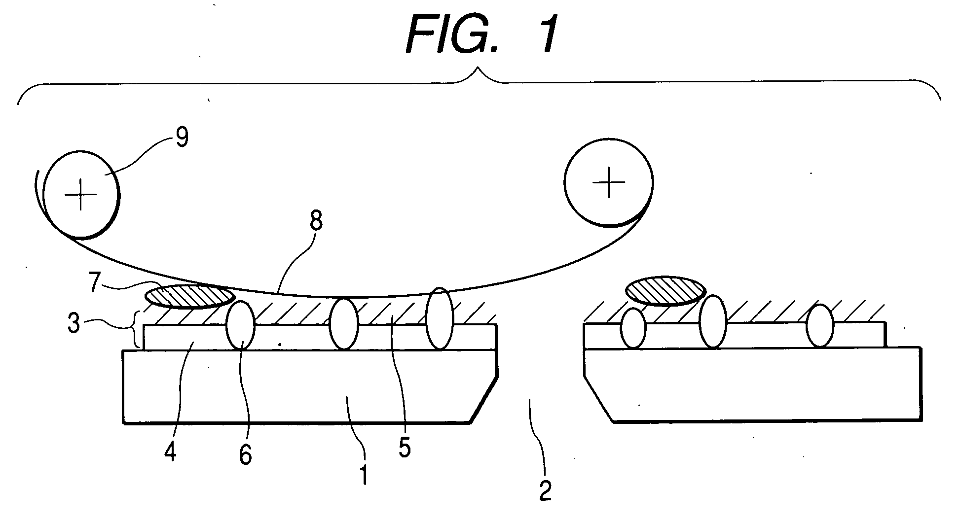
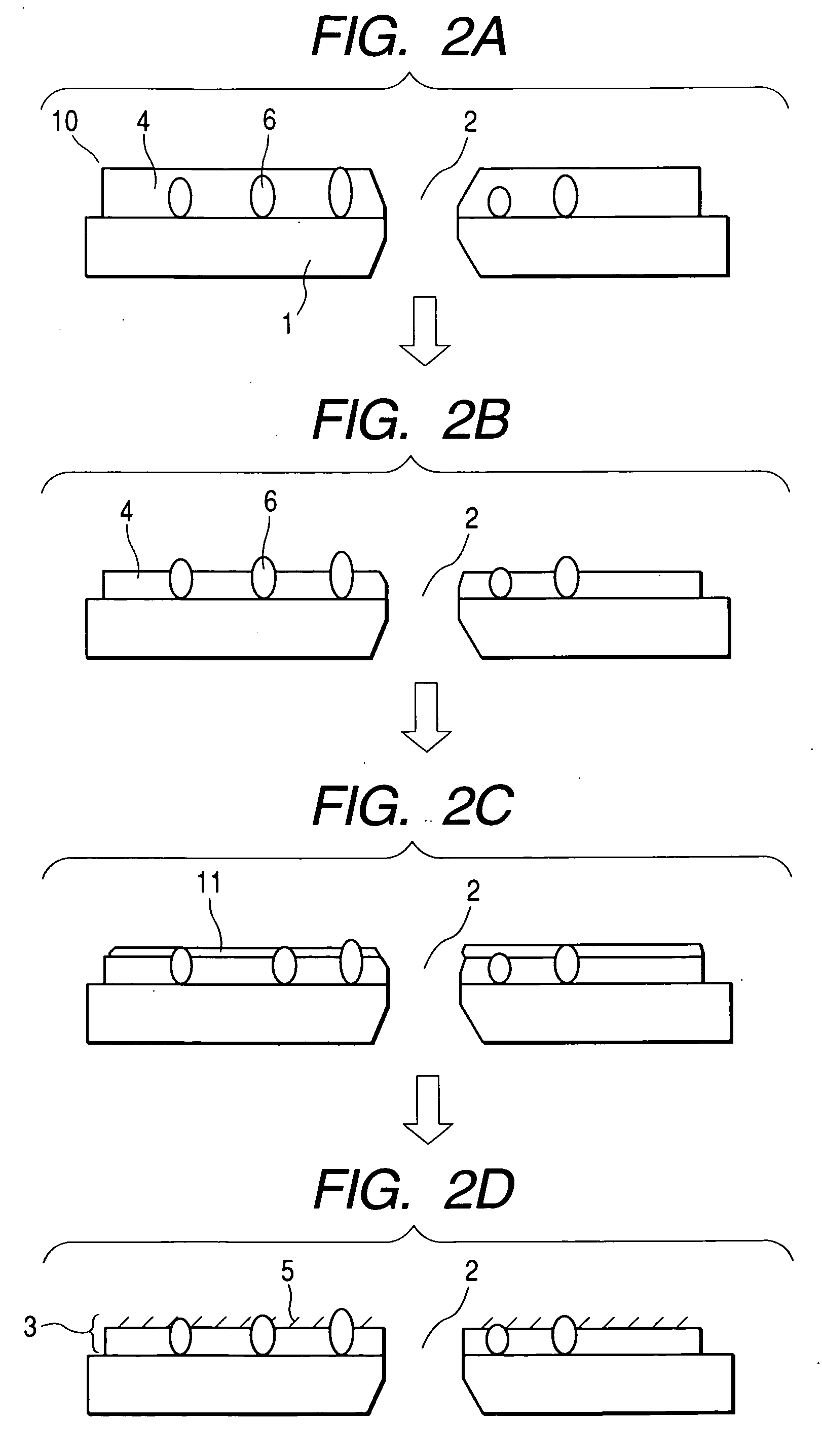
[0022] An ink-repellent film having an ideal configuration as shown in FIG. 1 will be illustrated in this example. FIG. 1 shows an ink-jet head according to the present invention at one moment during cleaning. The ink-jet head comprises a nozzle plate 1 and an ink-repellent layer 3. The nozzle plate 1 has nozzles 2 for discharging ink. The ink-repellent layer 3 comprises a resinous film 4, solid particles 6 and fluorocarbon polymer chains 5. The resinous film 4 serves also as an undercoat. The solid particles 6 protrude from the ink-repellent layer 3 to a specific height. The fluorocarbon polymer chains 5 are fibrous and protrude from the surface of the ink-repellent layer 3 in the form of whiskers.

[0023]FIG. 1 also shows part of a cleaning mechanism including a cleaning wiper 8 and a wind roll 9. Residual ink 7 remained on the ink-repellent layer 3 is in contact with the cleaning wiper 8 and is absorbed by the cleaning wiper 8. The cleaning wiper 8 is wound up by the wind roll 9. ...

example 2

[0034] The protrusion percentage of particles and the volumetric percentage of particles were investigated in detail as parameters affecting wear properties. The volumetric percentage of particles (%) can be said as an amount corresponding to gaps between the solid particles 6 when the resinous film 4 is observed from its surface. Specifically, films were prepared at volumetric percentages of particles of 20%, 40% and 60%, respectively, and the relation between the volumetric percentage of particles and the protrusion percentage of particles was determined. The result is shown in FIG. 5. The diagonally shaded area in FIG. 5 is an area of conditions under which the relative fluorine intensity stands at 0.8 to 1 even after repetitive cleaning procedures. The ink can be stably jetted from the ink jet nozzles under these conditions, namely, under such conditions that the relative fluorine intensity stands at 0.8 or above even after repetitive cleaning procedures.

[0035] The resulting hy...


PUM


Abstract

An ink-jet printer head is characterized by comprising an organic film coated on the surface of the nozzle plate for discharging ink, in which solid particles having abrasion resistance are dispersed, and a water-repellent film on the surface of the organic film, in which the chains of fluorocarbon polymer is grown. The head shows improved durability of the chains of the fluorocarbon polymer on the nozzle plate during cleaning of the nozzle surface.

Description

FIELD OF THE INVENTION [0001] The present invention relates to an ink-jet printer head and a manufacturing method thereof, more specifically, it relates to a technique of prolonging the lifetime of an ink-repellent surface of a nozzle surface. BACKGROUND OF THE INVENTION [0002] Ink-jet printer heads of prior art comprise nozzle orifices for discharging ink, ink chambers communicated to the nozzle orifices, and actuators, such as piezoelectric elements or heating elements, for pressurizing the ink chambers. Upon input of a recording signal, the nozzle orifices discharge droplets of ink to record information on a medium. In this technique, the dimensions and dimensional accuracy of the nozzle orifices, from which the ink droplets are discharged, affect the dimensions and dimensional accuracy of the jetted ink droplets. [0003] In addition, the properties of a surface of a member forming the nozzle orifices, particularly of a surface around the nozzle orifices, significantly affect the ...

Claims


Application Information

Patent Timeline
Patent Type & Authority Applications(United States)
IPC IPC(8): B41J2/14B41J2/16
CPCB41J2/1606B41J2/1433
Inventor TAMAHASHI, KUNIHIROOUCHI, AKEMIMAEKAWA, TSUTOMUFUJII, HIDETOSHISASAKI, HIROSHI
Owner RICOH KK
Why Eureka
Try Eureka