FSK demodulator system and method

a demodulator and fsk technology, applied in the field of fsk demodulator, can solve the problems of increasing the overall complexity and power dissipation of the tracking pll, the silicon area of a fully integrated lc tank discriminator is prohibitive for practical applications, and the design does not perform well with integrated receiver architectures

Active Publication Date: 2005-04-28
ANALOG DEVICES INC
View PDF6 Cites 41 Cited by
  • Summary
  • Abstract
  • Description
  • Claims
  • Application Information

AI Technical Summary

Benefits of technology

[0031] In one embodiment, the system may include an adder circuit responsive to the plurality of scaling circuits for lineally combining the outputs of each of the plurality of correlators for generating the lineally combined composite response. The analog-to-digital converter may include a limiter, the analog-to-digital converter may include a saturated analog-to-digital converter. The system may include a low pass filter response to the adder circuit for removing noise and harmonics from the lineally combined composite response.

Problems solved by technology

The result is an increase in the overall complexity and power dissipation of the tracking PLL.
Such a design does not perform well with integrated receiver architectures that operate with near zero IF due to the large time constants involved.
Moreover, while tuned LC tank resonators have been successfully integrated in CMOS technology, the silicon area of a fully integrated LC tank discriminator is prohibitive for practical applications.
The LC tuned circuit also consumes significant power and does not operate well with low power and / or low IF receiver designs.
Operating at zero IF produces DC offset and the problems associated therewith, as well as low frequency noise when CMOS technology is employed.
However, at high IF the power dissipation becomes a problem.
However, implementing the DC offset correction loop requires an additional analog-to-digital converter, amplifier and filter which increases the overall complexity and power dissipation of the system.

Method used


Image

  • FSK demodulator system and method
  • FSK demodulator system and method
  • FSK demodulator system and method

Examples


Embodiment Construction

[0041] Aside from the preferred embodiment or embodiments disclosed below, this invention is capable of other embodiments and of being practiced or being carried out in various ways. Thus, it is to be understood that the invention is not limited in its application to the details of construction and the arrangements of components set forth in the following description or illustrated in the drawings.

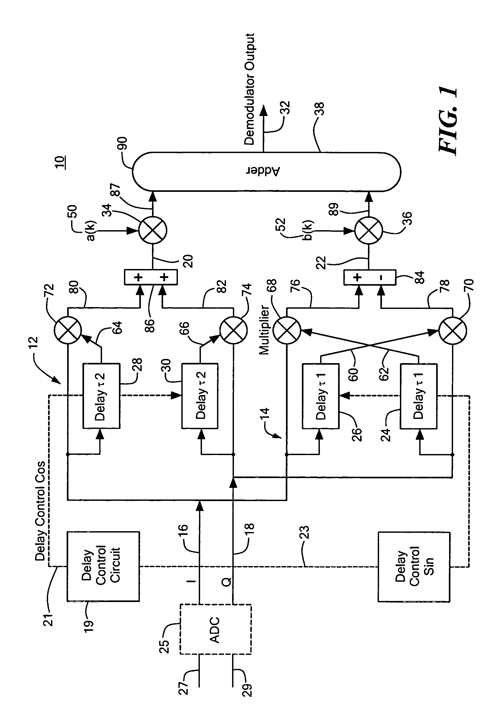
[0042] There is shown in FIG. 1, FSK demodulator system 10 of this invention with tunable spectral shaping. System 10 includes a pair of quadri-correlators, such as cosine correlator 12 and sine correlator 14, each of which are responsive to first quadrature signal (I) on line 16 and second quadrature signal (O) on line 18. The first and second quadrature signals on lines 16 and 18 are typically digital signals which have been converted from first and second quadrature signals on lines 27 and 29 by analog-to-digital converter 25. Ideally, analog-to-digital converter 25 is a limiter or a s...


PUM


Abstract

An FSK demodulator system with tunable spectral shaping including a pair of quadri-correlators responsive to first and second quadrature signals, one of the pair deriving first and second signals representative of the frequency deviation of the quadrature signals at even integer multiples of the frequency deviation and for resolving the modulated FSK data represented by the quadrature signals and the other of the pair deriving first and second signals representative of the frequency deviation of the quadrature signals at odd integer multiples of the deviation frequency and for resolving the modulated FSK data represented by the quadrature signals, and a delay control circuit for setting a delay to each of the pair of quadri-correlators to control the first and second signals representative of the frequency deviation of the quadrature signals derived by each of the pair of quadri-correlators and generate a tuned spectral response at both even and odd integer multiples of the frequency deviation.

Description

RELATED APPLICATIONS [0001] This application claims priority of U.S. Provisional Application No. 60 / 501,444 filed Sep. 9, 2003, and U.S. Provisional Application No. 60 / 563,031 filed Apr. 16, 2004, both incorporated by reference herein.FIELD OF THE INVENTION [0002] This invention relates generally to an FSK demodulator and more particularly to an improved FSK demodulator system and method with programmable spectral shaping. BACKGROUND OF THE INVENTION [0003] Frequency shift keying (FSK) modulation is a method often used to transmit digital data over a communications link. The data is typically transmitted on a carrier signal which includes positive and negative frequency deviations that represent the digital data. FSK demodulation is a technique used to extract the digital representation of the transmitted data by measuring the frequency deviations. [0004] Typical prior art techniques for FSK demodulation include, inter alia, tracking PLLs, tuned LC tank discriminators, matched filte...

Claims


Application Information

Patent Timeline
Patent Type & Authority Applications(United States)
IPC IPC(8): G01R23/00H04L27/14H04L27/156H04L27/22
CPCH04L27/156H04L27/144H03D3/02H03D3/007H04L27/1525
Inventor QUINLAN, PHILIP E.MULVANEY, KENNETH J.CROWLEY, PATRICK G.HUNT, WILLIAM
Owner ANALOG DEVICES INC
Why Eureka
Try Eureka