

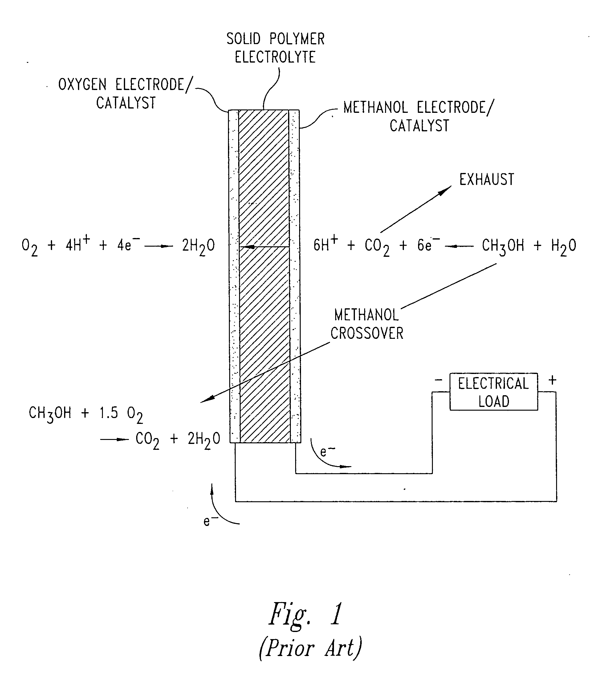
Fuel cells having silicon substrates and/or sol-gel derived support structures
- Summary
- Abstract
- Description
- Claims
- Application Information
AI Technical Summary
Benefits of technology
Problems solved by technology
Method used
Image

Examples
example 1
Silicon Substrate Electrode Assembly with Spanning Bridge Members
[0170] This example discloses the processing steps associated with making a membrane electrode assembly adapted for use with a fuel cell, wherein the membrane electrode assembly comprises: a planar anode made from a silicon substrate; an electrolyte layer; a planar cathode made from a silicon substrate; and optionally a blocking layer that is substantially impermeable to at least methanol and is substantially permeable to protons; wherein the planar anode and the planar cathode are spaced apart and substantially parallel to each other so as to define a spaced apart region, wherein the electrolyte layer and optional blocking layer are interposed between the planar anode and the planar cathode and within at least a portion of the spaced apart region, and wherein the planar anode and the planar cathode are attached to each other by at least one bridge member that spans across the spaced apart region.
[0171] In this examp...
example 2
Silicon Substrate Electrode Assembly
[0301] This example discloses the processing steps associated with making an membrane electrode assembly adapted for use with a fuel cell, wherein the membrane electrode assembly comprises: a planar anode made from a silicon substrate; an electrolyte layer; a planar cathode made from a silicon substrate; and optionally a blocking layer that is substantially impermeable to at least methanol and is substantially permeable to protons; wherein the planar anode and the planar cathode are spaced apart and substantially parallel to each other so as to define a spaced apart region, wherein the electrolyte layer and optional blocking layer are interposed between the planar anode and the planar cathode and within at least a portion of the spaced apart region.
[0302] In this example, the processing steps consist essentially of (1) the anode fabrication steps, (2) the cathode fabrication steps, and (3) the anode / electrolyte / cathode fabrication steps. However...
example 3
Sol-Gel Support Structure Electrode Assembly with Spanning Bridge Members
[0311] This example discloses an electrode assembly adapted for use with a fuel cell, wherein the membrane electrode assembly comprises: a planar anode made from a sol-gel derived support structure; an electrolyte layer; a planar cathode made from a sol-gel derived support structure; and optionally a blocking layer that is substantially impermeable to at least methanol and is substantially permeable to protons; wherein the planar anode and the planar cathode are spaced apart and substantially parallel to each other so as to define a spaced apart region, wherein the electrolyte layer and optional blocking layer are interposed between the planar anode and the planar cathode and within at least a portion of the spaced apart region, and wherein the planar anode and the planar cathode are attached to each other by at least one bridge member that spans across the spaced apart region.
[0312] In this example, the proc...
PUM
 Abstract
Description
Claims
Application Information