Optical element, optical pickup device and optical information recording and reproducing apparatus

a pickup device and optical pickup technology, applied in the field of optical elements, can solve the problems of increasing the change of spherical aberration per unit wavelength of diffractive structure, increasing the manufacturing cost of laser light sources, and increasing the manufacturing cost of optical pickup devices, so as to improve the yield in mass production of laser light sources and reduce manufacturing costs

Inactive Publication Date: 2005-05-05
KONICA MINOLTA OPTO
View PDF10 Cites 15 Cited by
  • Summary
  • Abstract
  • Description
  • Claims
  • Application Information

AI Technical Summary

Benefits of technology

[0011] In view of the problems stated above, an object of the invention is to make it possible to control an amount of changes of spherical aberration per unit wavelength change, and thereby to provide an optical element, an optical pickup device and an optical information recording and reproducing apparatus wherein the yield in mass production of laser light sources is improved and manufacturing cost can be reduced.

Problems solved by technology

Nevertheless, when using the diffractive structure that generates diffracted light with combination of diffraction order number n1 and diffraction order number n2 both satisfying the aforesaid relationship, for realizing compatibility between a high density optical disk and DVD, an amount of change of spherical aberration per unit wavelength of the diffractive structure grows greater, thus, the laser light source needs to be selected, resulting in the problem that an increase in manufacturing cost for the laser light source and an increase in manufacturing cost for the optical pickup device are caused.

Method used


Image

  • Optical element, optical pickup device and optical information recording and reproducing apparatus
  • Optical element, optical pickup device and optical information recording and reproducing apparatus
  • Optical element, optical pickup device and optical information recording and reproducing apparatus

Examples


example 2

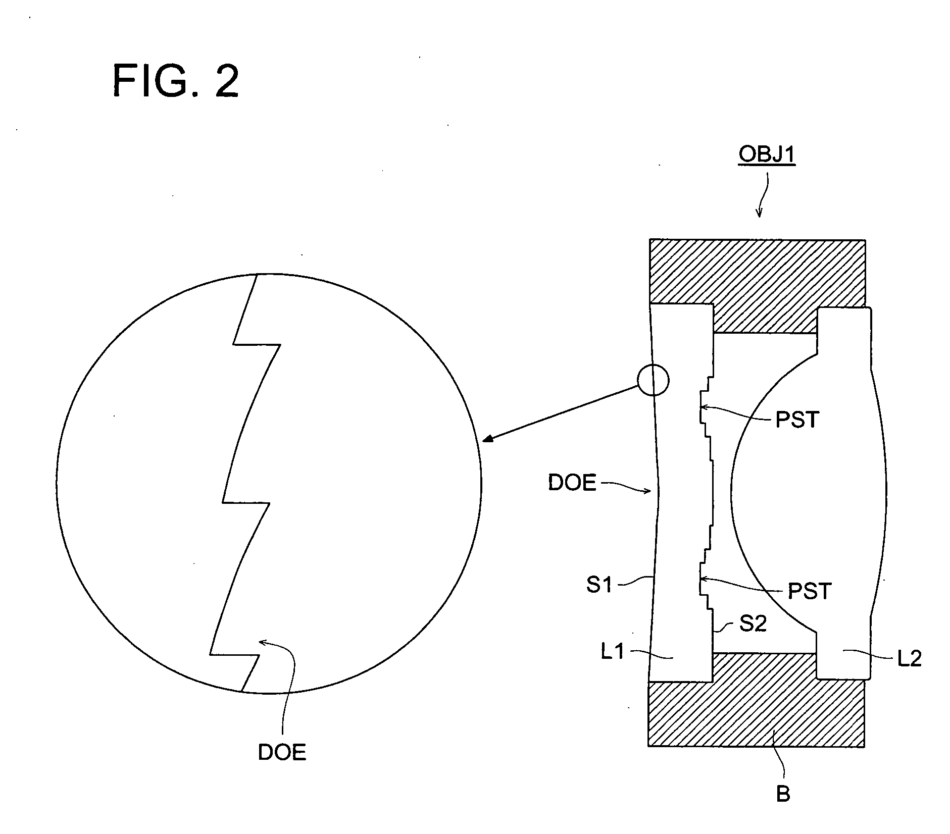
[0282] Table 3 shows lens data of Example 2 of the invention, and FIG. 11 shows an optical path diagram. The present example is composed of the first aberration correcting element L1 on which diffractive structure DOE is formed, the second aberration correcting element L2 on which optical path difference providing structure PST is formed and of light-converging element L3. Each of the first aberration correcting element L1 and the second aberration correcting element L2 is a plastic lens, and the light-converging element L3 is a glass lens.

(Table 3)

[0283] (Optical specifications) [0284] HD:NA1=0.85, f1=1.765 mm, λ1=405 nm, m1=0, t1=0.1 mm [0285] DVD:NA2=0.65, f2=1.807 mm, λ2=655 nm, m2=0, t2=0.6 mm

[0286] (Paraxial data)

Surfacerd1d2No.(mm)(mm)(mm)Nλ1Nλ2νdOBJ∞∞STO0.50000.5000122.57851.00001.00001.5246941.50651356.52∞0.10000.10003∞1.00001.00001.5246941.50651356.54∞0.10000.100051.23692.14002.14001.6227171.60317561.26−3.31040.53070.30157∞0.10000.60001.6194951.57721030.08∞

[0287] (As...

example 3

[0296] Table 5 shows lens data of Example 3 of the invention, and FIG. 14 shows an optical path diagram. The present example is an objective optical system wherein a light-converging element that is made up of one group has a function of the optical element of the invention, and it is a plastic lens wherein diffractive structure DOE is formed on optical surface S1 of the plastic lens closer to the laser light source, and optical path difference providing structure PST is formed on optical surface S2 of the plastic lens closer to an optical disk.

(Table 5)

[0297] (Optical specifications) [0298] HD:NA1=0.67, f1=2.986 mm, λ1=405 nm, m1=0, t1=0.6 mm [0299] DVD:NA2=0.655, f2=3.070 mm, λ2=655 nm, m2=0, t2=0.6 mm

[0300] (Paraxial data)

Surfacerd1d2No.(mm)(mm)(mm)Nλ1Nλ2νdOBJ∞∞STO0.50000.500012.02492.30002.30001.5670151.54702355.02−9.16521.30201.35903∞0.60000.60001.6194951.57721030.04∞

[0301] (Aspheric surface coefficient)

Second surfaceSecond surfaceFirst ring-Second ring-Third ring-Fourt...


PUM

PropertyMeasurementUnit
refractive indexaaaaaaaaaa
thicknessaaaaaaaaaa
thicknessaaaaaaaaaa

Abstract

An optical element for use in an optical pickup device to conduct reproducing and/or recording information for a first disk including a protective substrate by the use of a first light flux emitted from a first light source and to conduct reproducing and/or recording information for a second disk including a protective substrate by the use of a second light flux emitted from a first light source, the optical element includes: an optical surface on which a first phase structure is formed to have a function to correct a spherical aberration; an optical surface on which a second phase structure is formed such that when the wavelength of the first light flux changes, the second phase structure generates a spherical aberration in a direction reverse to the direction of a spherical aberration generated by the first phase structure.

Description

FIELD OF THE INVENTION [0001] The present invention relates an optical element, an optical pickup device and an optical information recording and reproducing apparatus. [0002] There has so far been known an optical pickup device capable of conducting recording / reproducing for plural types of optical disks each being different from others in terms of recording density. An example of the optical pickup device is one which conducts recording / reproducing by using an optical pickup device for DVD (Digital Versatile Disk) and CD (Compact Disc). In recent years, there has been a demand for an optical pickup device that is compatible for a high density optical disk (hereinafter, optical disks using a violet laser light source as a laser light source are named generically as “high density disk”) using a violet laser light source (for example, a violet semiconductor laser or a violet SHG laser), conventional DVD and further for CD, as optical disks each being different from others in terms of...

Claims


Application Information

Patent Timeline
Patent Type & Authority Applications(United States)
IPC IPC(8): G02B5/18G02B13/00G02B13/18G11B7/00G11B7/125G11B7/135
CPCG11B7/1275G11B7/1353G11B7/1367G11B2007/0006G11B7/139G11B7/13922G11B7/1374G02B5/18
Inventor KIMURA, TOHRU
Owner KONICA MINOLTA OPTO
Why Eureka
Try Eureka