

Fiber device with high nonlinearity, dispersion control and gain
a fiber device and nonlinearity technology, applied in the field of optical fiber devices, can solve the problems of increasing the size, complexity, and cost of the system, and achieve the effects of low cost, stable modelocking, and high nonlinearity
- Summary
- Abstract
- Description
- Claims
- Application Information
AI Technical Summary
Benefits of technology
Problems solved by technology
Method used
Image

Examples
Embodiment Construction
[0037] A preferred embodiment and variations thereon will be disclosed in detail with reference to the drawings, in which like reference numerals refer to like elements or steps throughout.
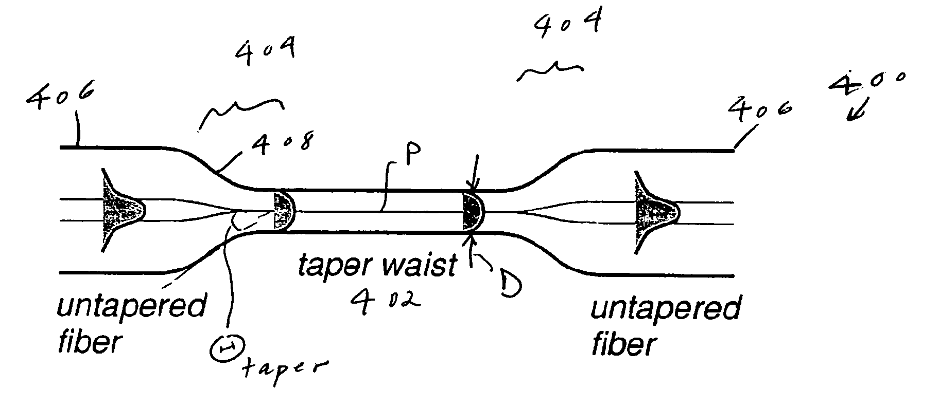
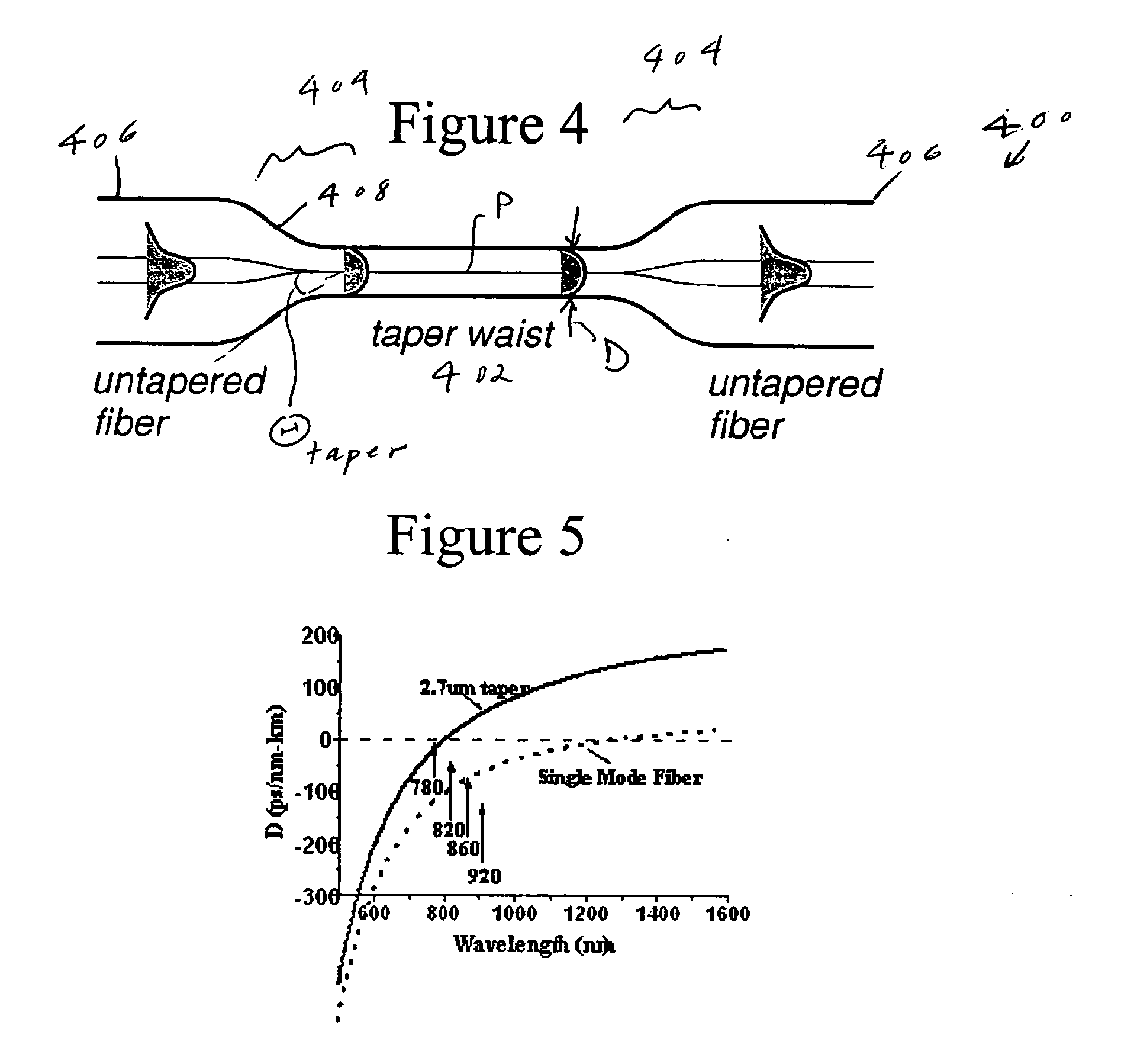
[0038]FIG. 4 shows a section of fiber 400 that has been tapered according to the preferred embodiment. The fiber 400 has a narrowed portion or taper waist 402 bounded by two taper regions or transition regions 404 that connect the taper waist 402 with non-tapered portions 406 of the fiber 400.
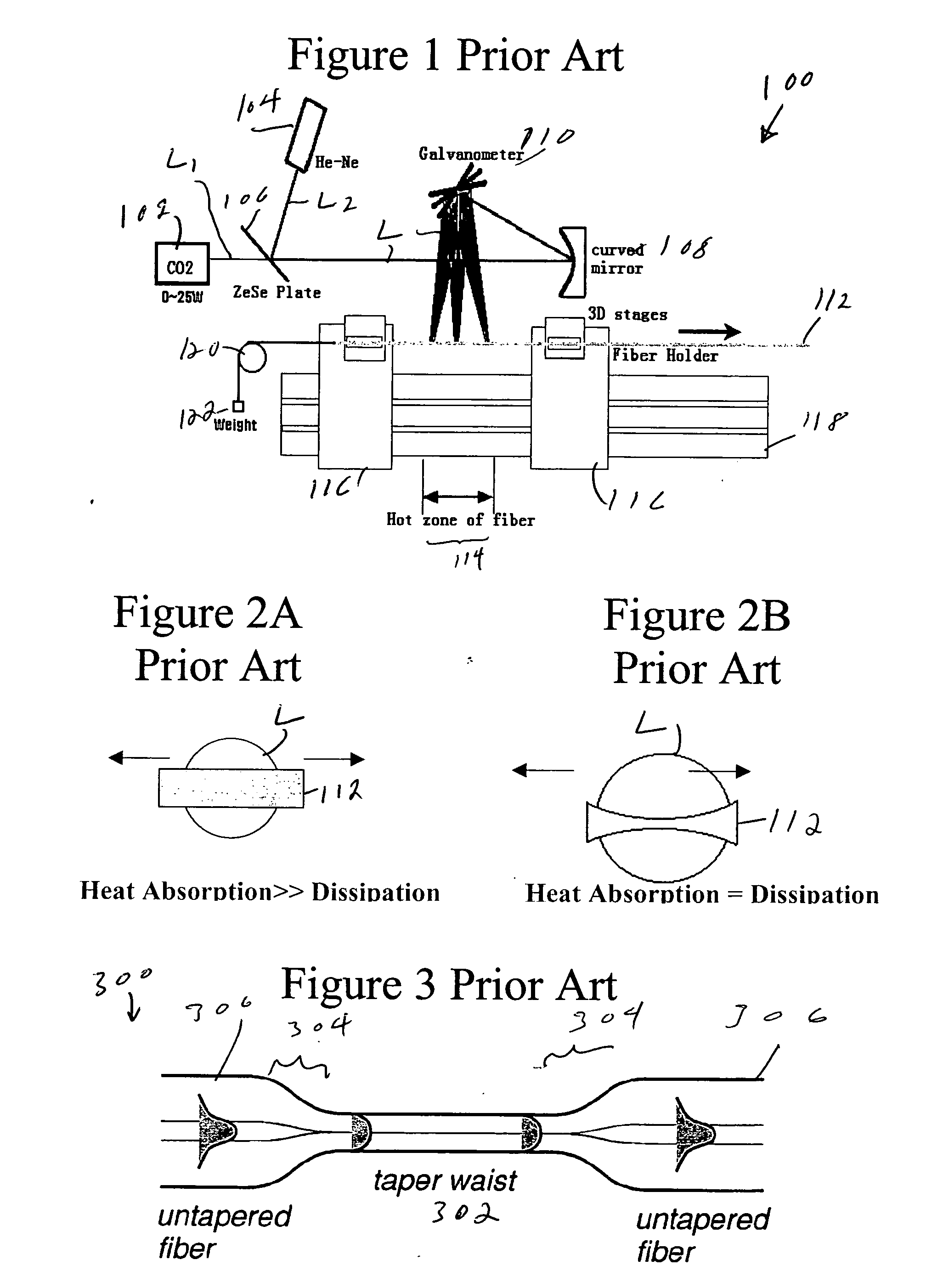
[0039] The design parameters distinguishing the fiber 400 of FIG. 4 from the fiber 300 of FIG. 3 are the taper angle Θtaper and the diameter D of the taper waist 402. Those design parameters can be controlled by suitable control of a tapering system like that of FIG. 1. Those design parameters have the following significance to loss, dispersion and nonlinearity.
[0040] Each transition region 404 has a taper angle Θtaper, which is defined as the angle between the outer surface 408 of the transition region 40...
PUM
| Property | Measurement | Unit |
|---|---|---|
| power | aaaaa | aaaaa |
| wavelength | aaaaa | aaaaa |
| diameter | aaaaa | aaaaa |
Abstract
Description
Claims
Application Information