Holey optical fiber with random pattern of holes and method for making same

a technology of optical fibers and random patterns, applied in the field of new techniques for making holey optical fibers with random patterns of holes, can solve the problems that the tube-stacking method cannot be used to produce fibers with random arrays of holes, and the complexity of assembling tubes, etc., and achieve the effect of increasing optical loss

Active Publication Date: 2005-05-05
VIRGINIA TECH INTPROP INC
View PDF12 Cites 76 Cited by
  • Summary
  • Abstract
  • Description
  • Claims
  • Application Information

AI Technical Summary

Problems solved by technology

One of the drawbacks of the conventional method for making holey optical fibers is the complexity of assembling the stack of tubes.
Also, the tube-stacking method cannot be used to produce fibers with random arrays of holes.

Method used


Image

  • Holey optical fiber with random pattern of holes and method for making same
  • Holey optical fiber with random pattern of holes and method for making same
  • Holey optical fiber with random pattern of holes and method for making same

Examples


Embodiment Construction

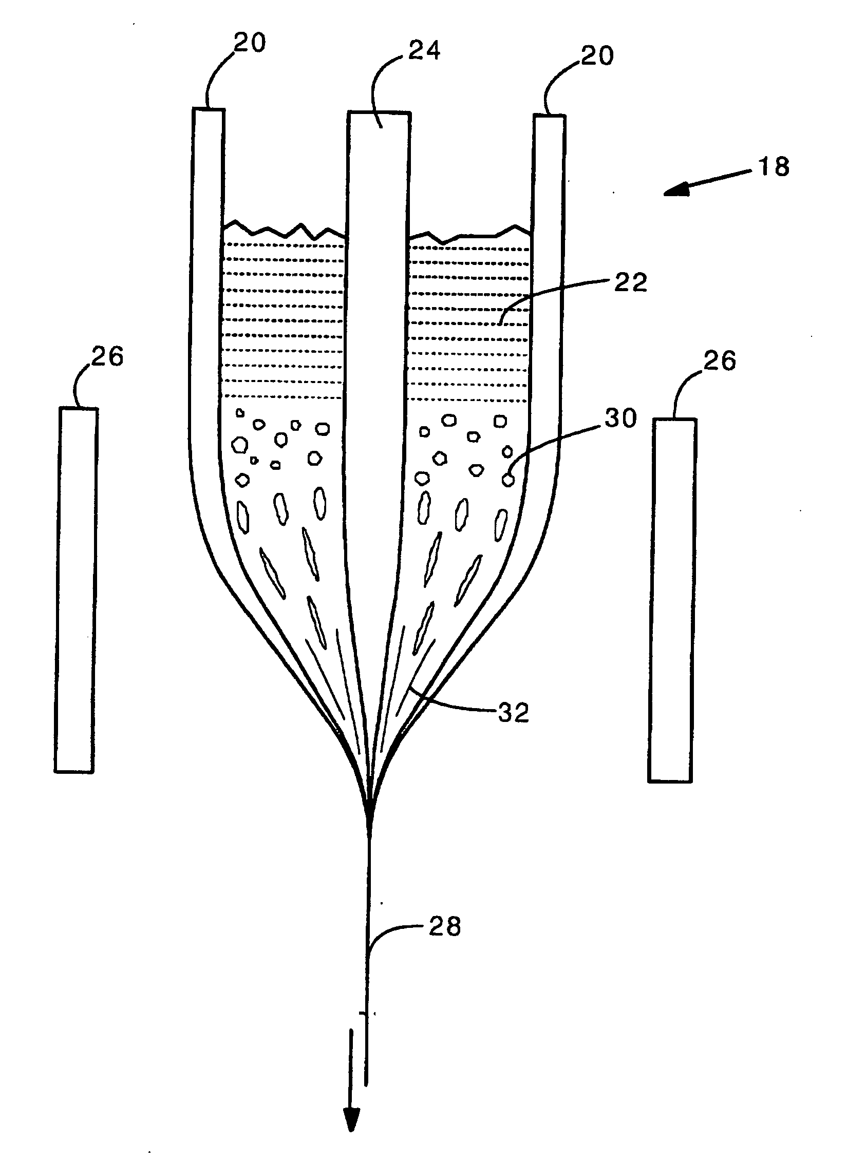
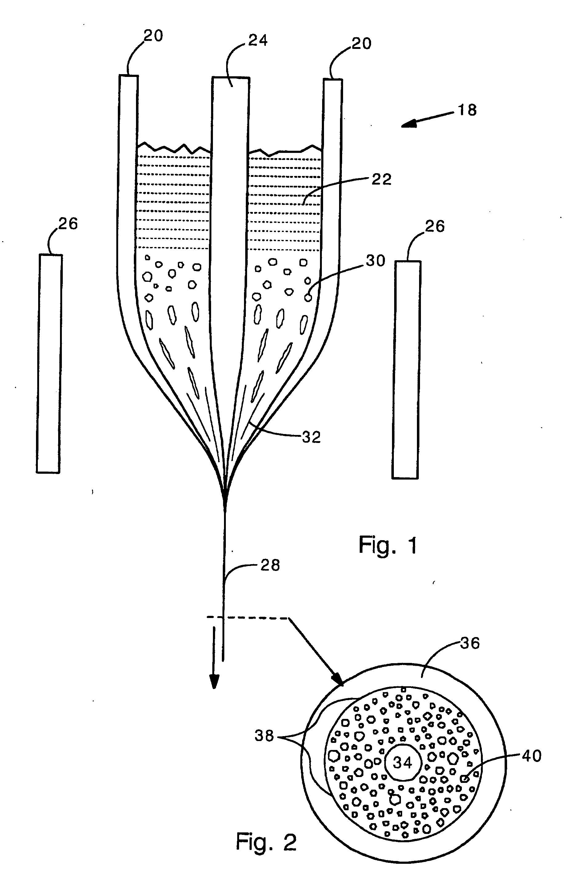
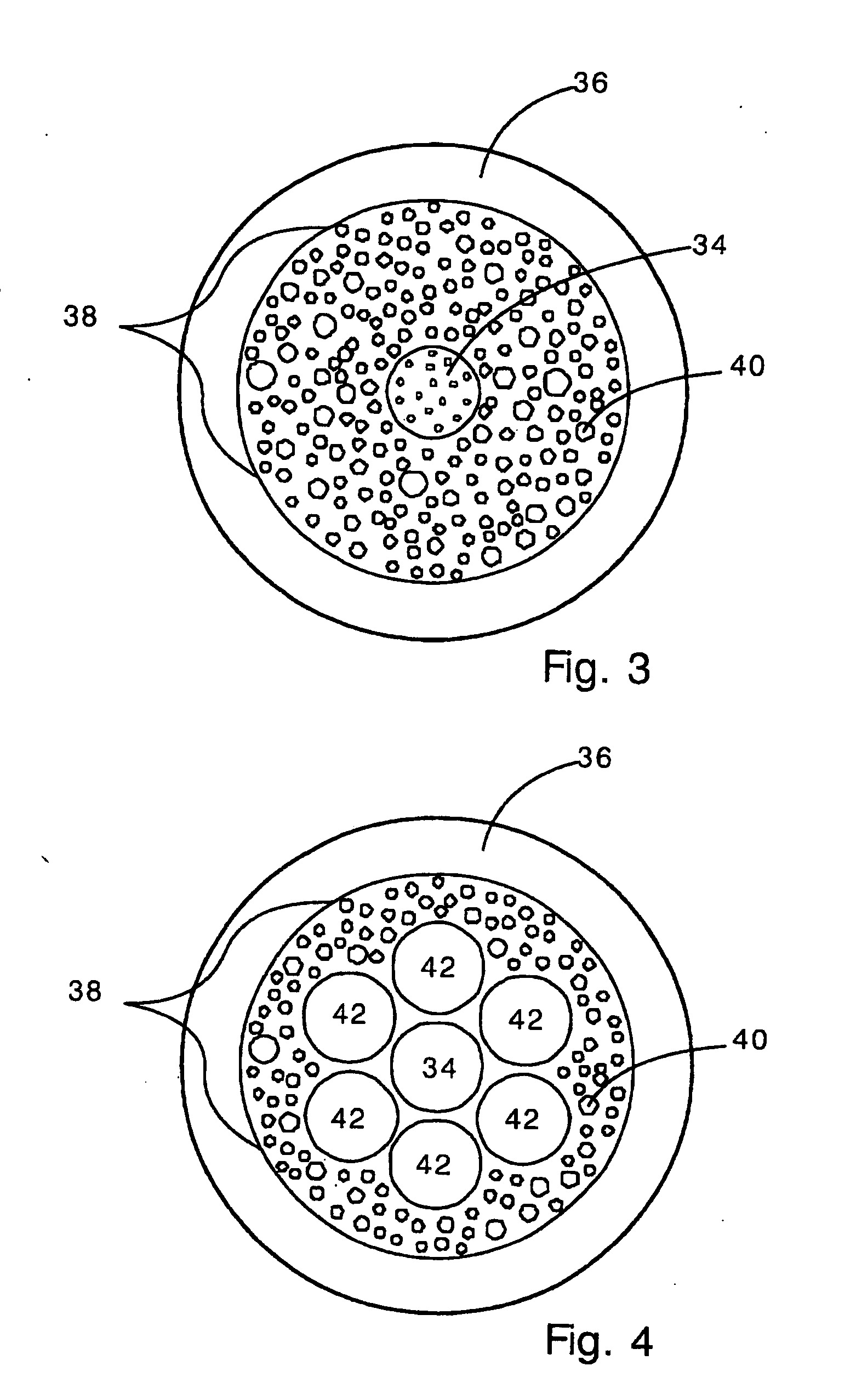
[0024] The present invention provides a holey optical fiber with a random array of holes. In the present invention, the holey optical fiber is made by including a gas-generating material in the fiber preform. In a typical embodiment, the gas generating material is located around a solid core (e.g., made of solid SiO2). The gas generating material may be a nitride ceramic (e.g., silicon nitride, rare earth nitrides, AlN, TiN) or carbide ceramic (e.g. silicon carbide, rare earth carbides) that decomposes at or close to the fiber drawing temperature (e.g., 1500-1600 Celsius in the case of pure fused silica fibers). Decomposition produces gas bubbles (e.g., N2, CO2, carbon monoxide or nitrogen oxides) in the molten preform material as it is drawn. The gas bubbles are randomly distributed and are drawn into long thin holes (or tubes) that remain in the optical fiber. The holes reduce the refractive index in the region surrounding the solid core, and so provide light confinement. The numb...


PUM

PropertyMeasurementUnit
wavelengthaaaaaaaaaa
weightsaaaaaaaaaa
weightsaaaaaaaaaa

Abstract

A random array of holes is created in an optical fiber by gas generated during fiber drawing. The gas forms bubbles which are drawn into long, microscopic holes. The gas is created by a gas generating material such as silicon nitride. Silicon nitride oxidizes to produce nitrogen oxides when heated. The gas generating material can alternatively be silicon carbide or other nitrides or carbides. The random holes can provide cladding for optical confinement when located around a fiber core. The random holes can also be present in the fiber core. The fibers can be made of silica. The present random hole fibers are particularly useful as pressure sensors since they experience a large wavelength dependant increase in optical loss when pressure or force is applied.

Description

CROSS-REFERENCE TO RELATED APPLICATIONS [0001] The present application claims the benefit of priority from co-pending provisional application 60 / 515,447, filed on Oct. 30, 2003.FIELD OF THE INVENTION [0002] The present invention relates generally to holey optical fibers and methods for making holey optical fibers. More specifically, the present invention relates to a new technique for making holey optical fibers having random patterns of holes. In the present method, a gas-generating material included in the fiber preform forms the holes as the fiber is drawn. BACKGROUND OF THE INVENTION [0003] Holey optical fibers have microscopic holes or voids for guiding light. In holey fibers, the core is solid (e.g. SiO2) and is surrounded by an array of holes containing inert gas or air. The light guided in the optical fiber may be confined to the central core region by one of two basic mechanisms. In the first mechanism, light is confined to the central core region by a refractive index diff...

Claims


Application Information

Patent Timeline
Patent Type & Authority Applications(United States)
IPC IPC(8): C03B37/012C03B37/027C03C11/00C03C13/04G02B6/02
CPCC03B37/01297G02B6/02295C03B2203/14C03B2203/42C03C11/007C03C13/04G01L1/243G02B6/02333G02B6/02338G02B6/02357G02B6/02366C03B37/016G02B6/02385G02B6/032C03B37/02781
Inventor PICKRELL, GARYKOMINSKY, DANIELSTOLEN, ROGERKIM, JEONG I.WANG, ANBOSAFAAI-JAZI, AHMAD
Owner VIRGINIA TECH INTPROP INC
Why Eureka
Try Eureka